Word Clock 1.0: Open Hardware Advent Calendar Day 13
Today’s late posting is brought to you by “unintentional napping”. It’s a project I finished a few years ago: a Word Clock.
Overview
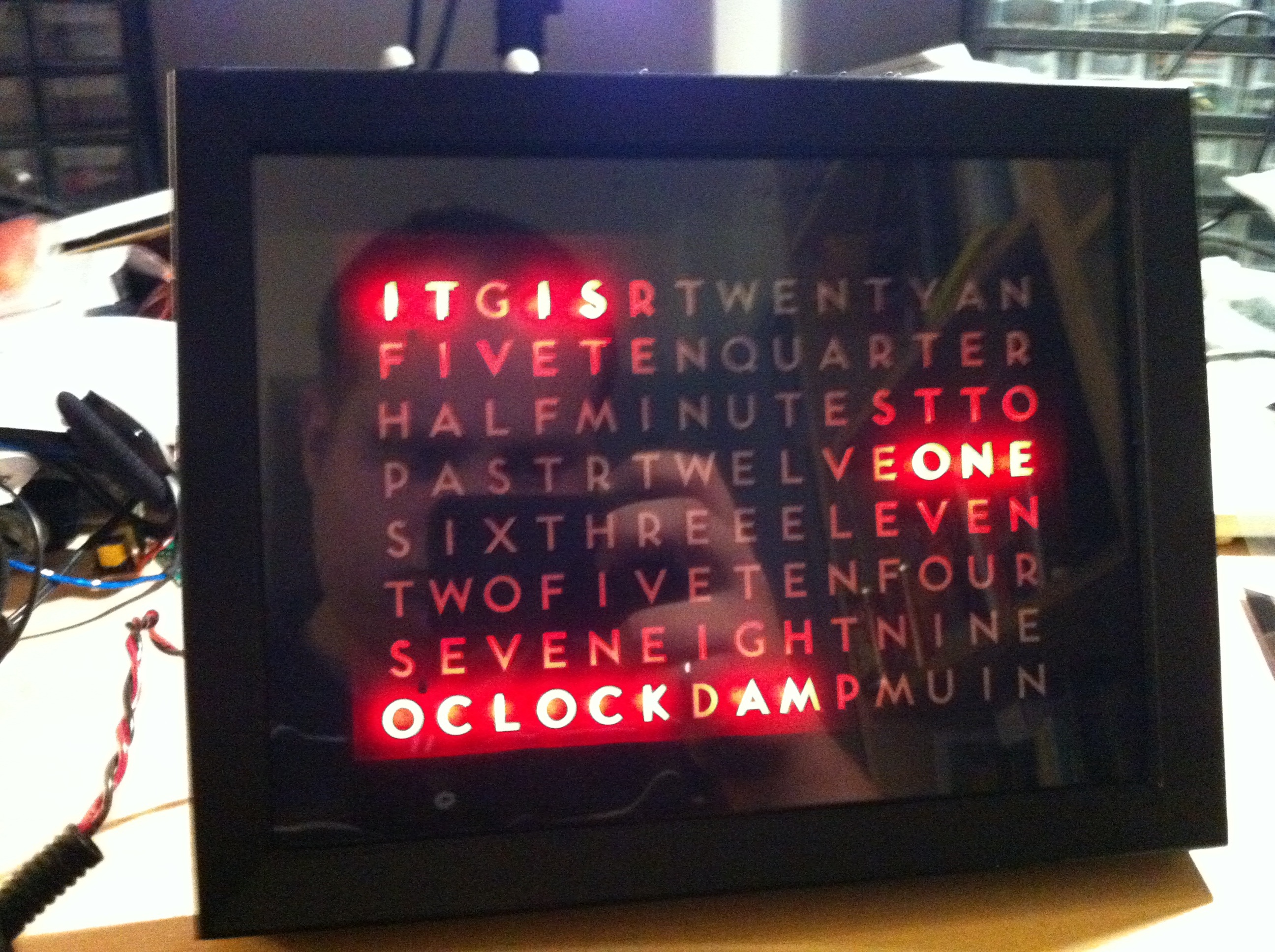
A word clock is a clock that is made of a bunch of letters. These letters for the words that spell out the time - “IT IS SIX OCLOCK”, “IT IS A QUARTER TO SEVEN”, etc. The letters each have a light behind them, so that the letters and words that are lit up spell out the time.

Mine, as with many, was inspired by the QLOCKTWO, in addition to others, like my friend James’ Antelope clock.
Hardware
This version is Arduino-based (using an ATMEGA328 running at 8 MHz), using a Microchip MCP79410 real-time clock chip for timekeeping. The Arduino is connected to four buttons for setting the time and changing the display to show the number of seconds. It also reads from a TEPT4400 ambient light sensor to control the overall brightness of the clock.
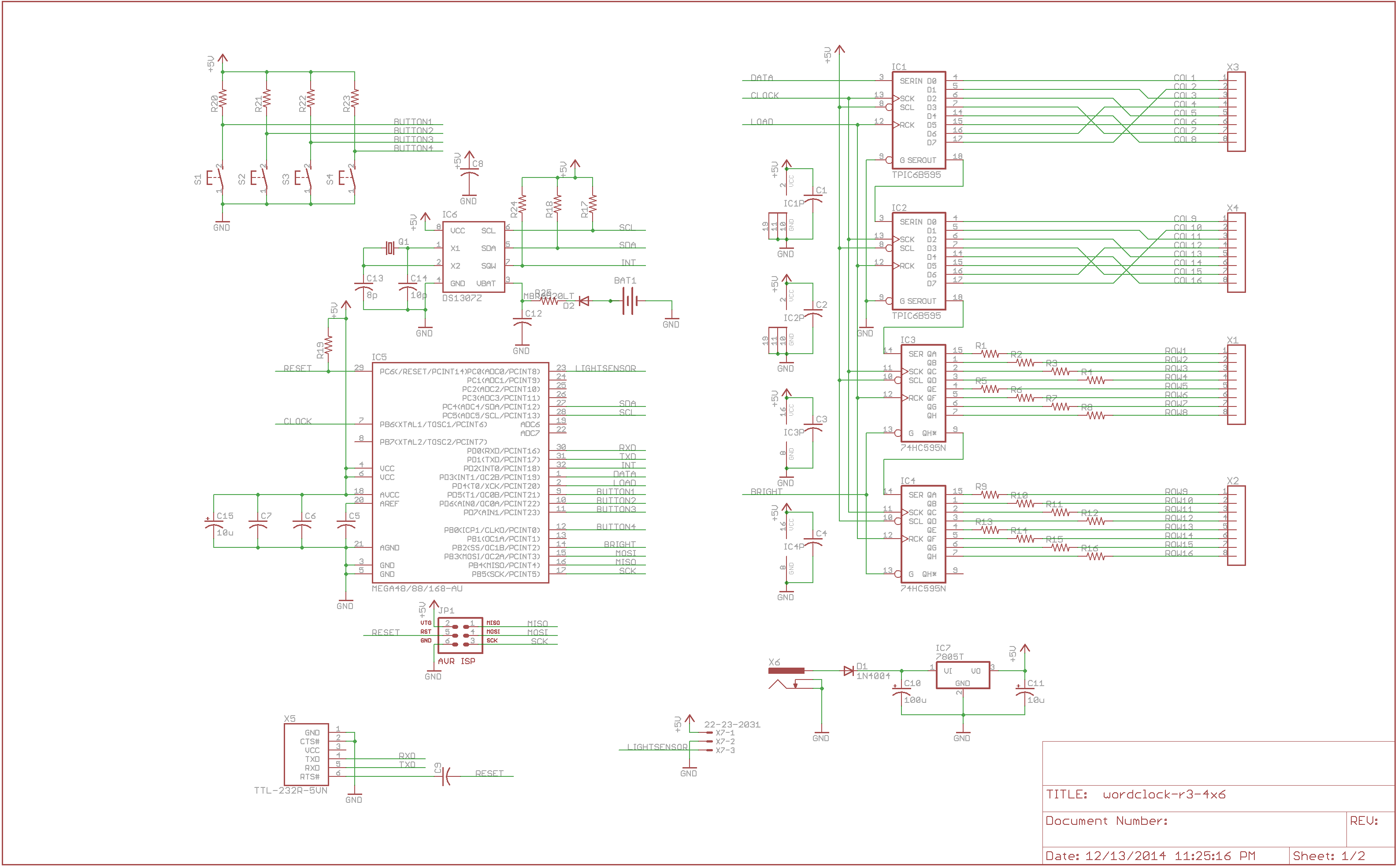
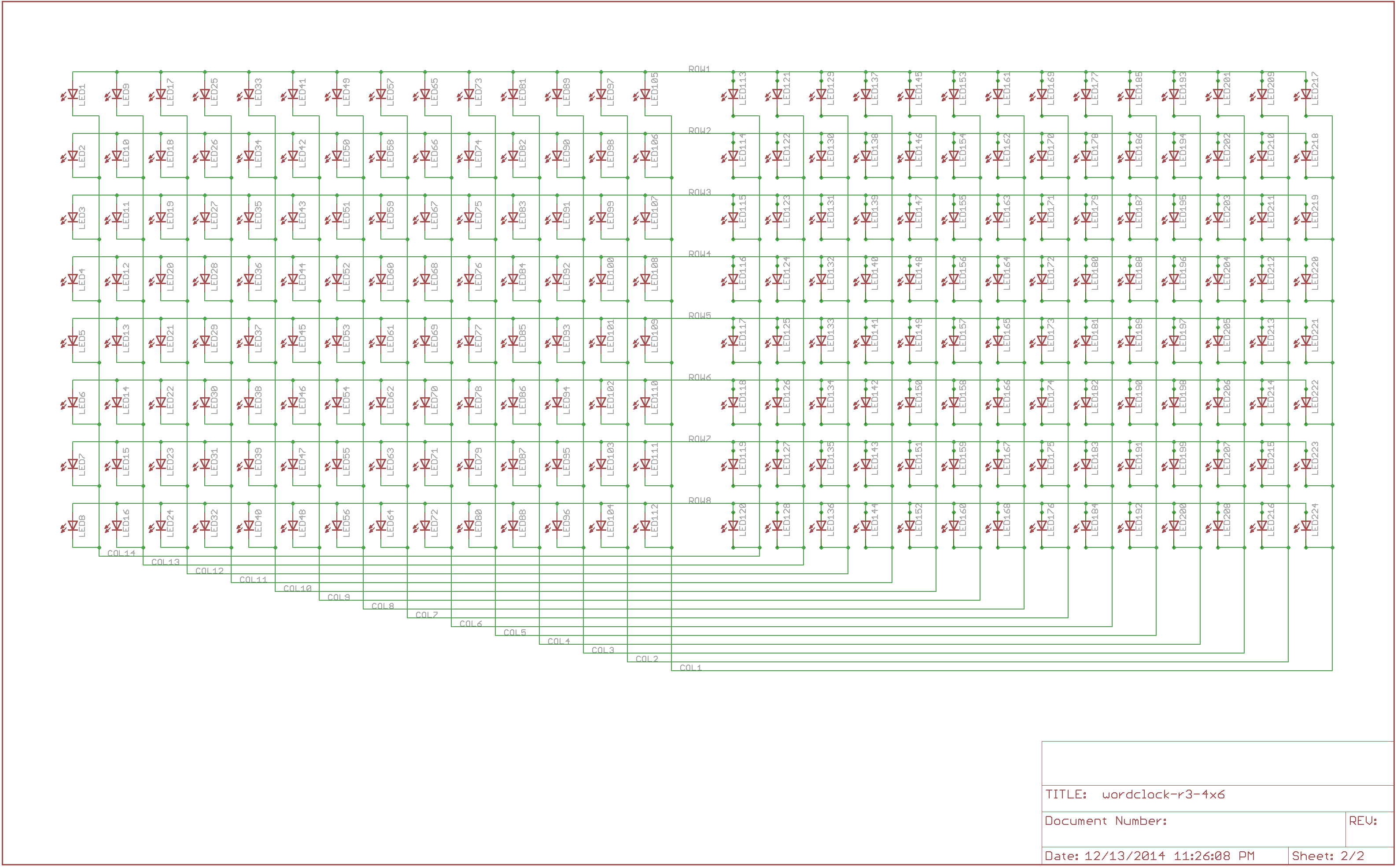
The Arduino drives the display control circuit, as well. This is formed of two TPIC6B595 power shift registers (shift registers with MOSFETs on their outputs to act as low-side drives) and a 74HC595 shift register to drive the high side of the LEDs. The schematic and board provide for two 74HC595s, but only one is used in the assembled clock. The display is scanned one column at a time, for each of the 16 columns of 8 LEDs each. The LED array is made with both through-hole and surface mount (3528 package) footprints to allow either kind of LED to be used.
A very basic 7805 circuit provides a stable 5V supply.
The board used was not designed for any particular enclosure. This means that it doesn’t fit any known enclosure all that well. As you can imagine, this became an issue during final assembly.
Schematic and PCB files can be found on our GitHub.
Software
The software is a fairly self-contained Arduino project - RTC code is included, so the only real external dependency is the Wire library included with the Arduino software. A bootloader needs to be flashed onto the ATMega328 to load the firmware - a script to do so and the bootloader HEX file are also provided.
Source code can be found on our GitHub.
The software handles a setup mode for setting the time, displaying the time as words, and displaying the number of seconds on the display (using the letters as pixels to form numbers) when the Seconds button is pressed (S4 on the schematic).
To set the time, S1 is pushed, to put the clock in set mode. The top two letters on the left indicate that you’re adjusting hours, and the Up (S3) and Down (S2) buttons are used to adjust the hours up and down. Pressing S1 again moves to setting Minutes, and then Seconds. Pressing S1 one more time saves the time and returns to display mode. Pressing S4 at any time while setting will cancel set mode. Waiting more than 45 seconds will cancel as well.
RenderTimeMatrixV1BetaGrid.cpp sets up the mapping of words to the LEDs - it contains a number of conditions to determine which words to light up. For moving to different languages, this should be the only file that needs to be edited. The English artwork for the letter grid is included in the source code.
Physical construction
Rather than laser etching and other methods for creating the letter grid overlay (which require tools that we don’t have), we used old-fashioned overhead transparencies. Two were stacked on each clock - one laser-printed (which blocks light better), and one inkjet (which doesn’t block light as well, but looks black rather than gray).
The transparencies are mounted in a photo frame that fits the board - we got one from Dollarama - directly behind the glass. Behind the transparencies is a sheet of kitchen parchment paper, to act as a diffuser. This sandwich is held against the glass with a thick paper frame, and the plastic spacer that came with the frame.
(photos of this stackup will be posted at a later date)
Artwork in English is posted to GitHub.
Future plans
I’ve pretty much given up on this design. A major shortcoming is that it drives only 8 LEDs at a time, in 16 rows. This means that each LED is only on 1/16 of the time - so you need to drive a LOT of current to get acceptable brightness. Switching it around - so that 16 LEDs are driven at a time, 1/8th of the time - would mean we could get an acceptable display brightness without stressing the LEDs as much. I also want to make one that can be mounted in a particular enclosure nicely, rather than hacking apart a dollar store photo frame as I had to do.
Version 2 is already being planned, and will hopefully be done in early 2015.
Conclusion
This design works, but maybe not as well as we’d like. We don’t suggest anyone build it, as we’ve got something better coming - something that had evolved a lot based on the lessons from this project. Some of the parts we played with - the Microchip RTCs, for example - worked really well, and we’ll be using them again. The RTCs especially are far cheaper than the Maxim equivalent. The power shift registers, while nice, aren’t really worth the extra cost.
Stay tuned for Word Clock 2.0.