USBTinyISP alternate PCB: Open Hardware Advent Calendar Day 3
Today wound up being dominated by getting a parts order in for more interesting projects, so it’s another boring one for the day. This is basically just an alternative circuit board design for Adafruit’s USBTinyISP AVR programmer.
Overview
Electrically, this is identical to Adafruit’s board - uses the same schematic and everything. The actual board layout is vastly different, however. The biggest change is that rather than a double-sided layout with wiring on both sides of the board, this one is single-sided. This is because while I was at McMaster University, and didn’t have tons of money, I did have access to a circuit board milling machine. This takes a copper-clad circuit board, and uses a rotating milling bit to carve grooves in the copper to isolate the printed circuit pattern. This let us make our own boards for not a lot of money.
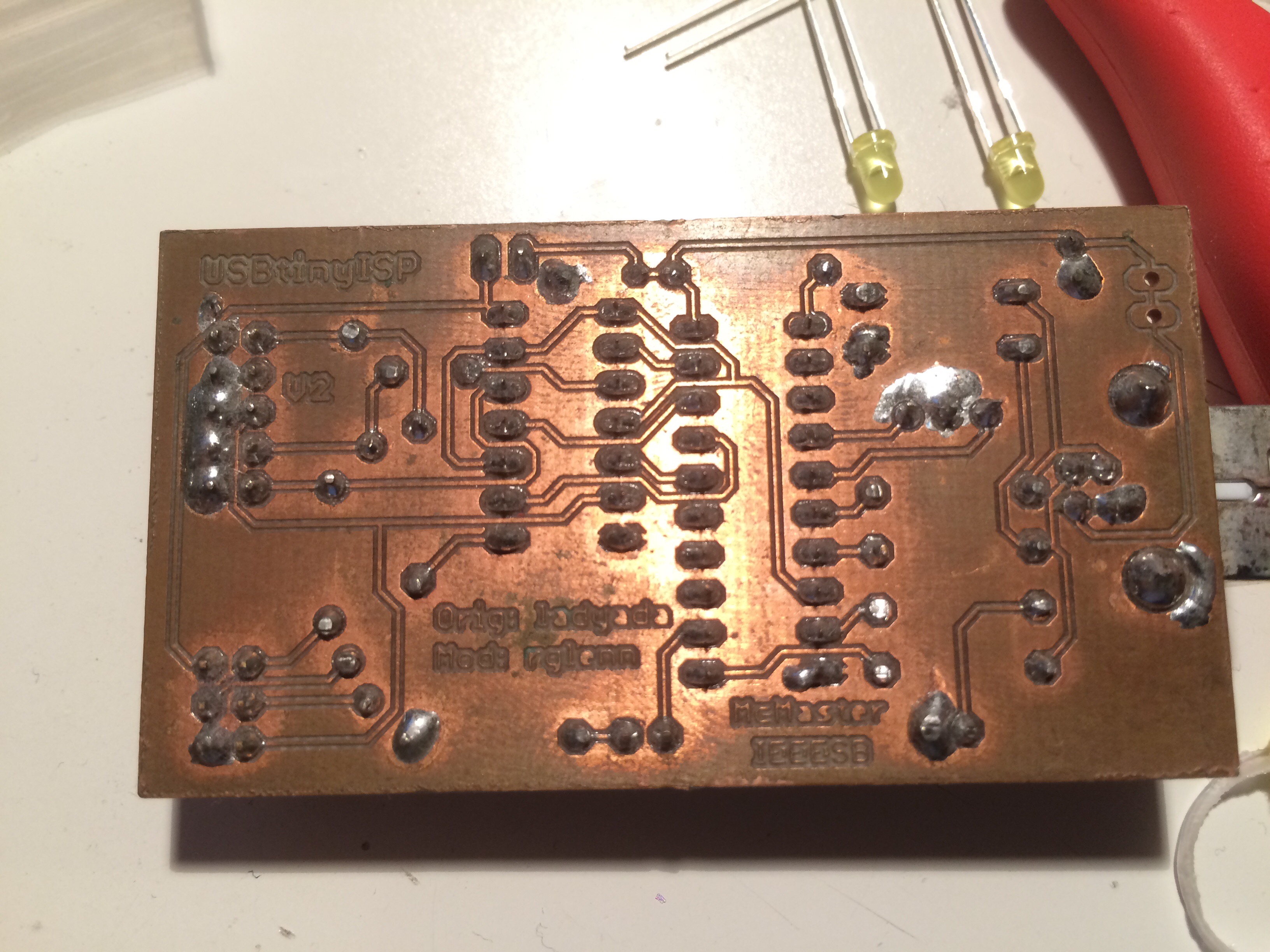
The catch of this machine, though, was that doing both sides of the board was really complicated. There was a lot of work making sure that things would line up properly when you flip the board over, and the system for adding a metal plating to the holes going through the board so that both sides connect was tricky. Normally, when you get boards made at a factory, this is handled chemically. So sticking with single-sided designs on the milling machine was for the best.
Building the hardware
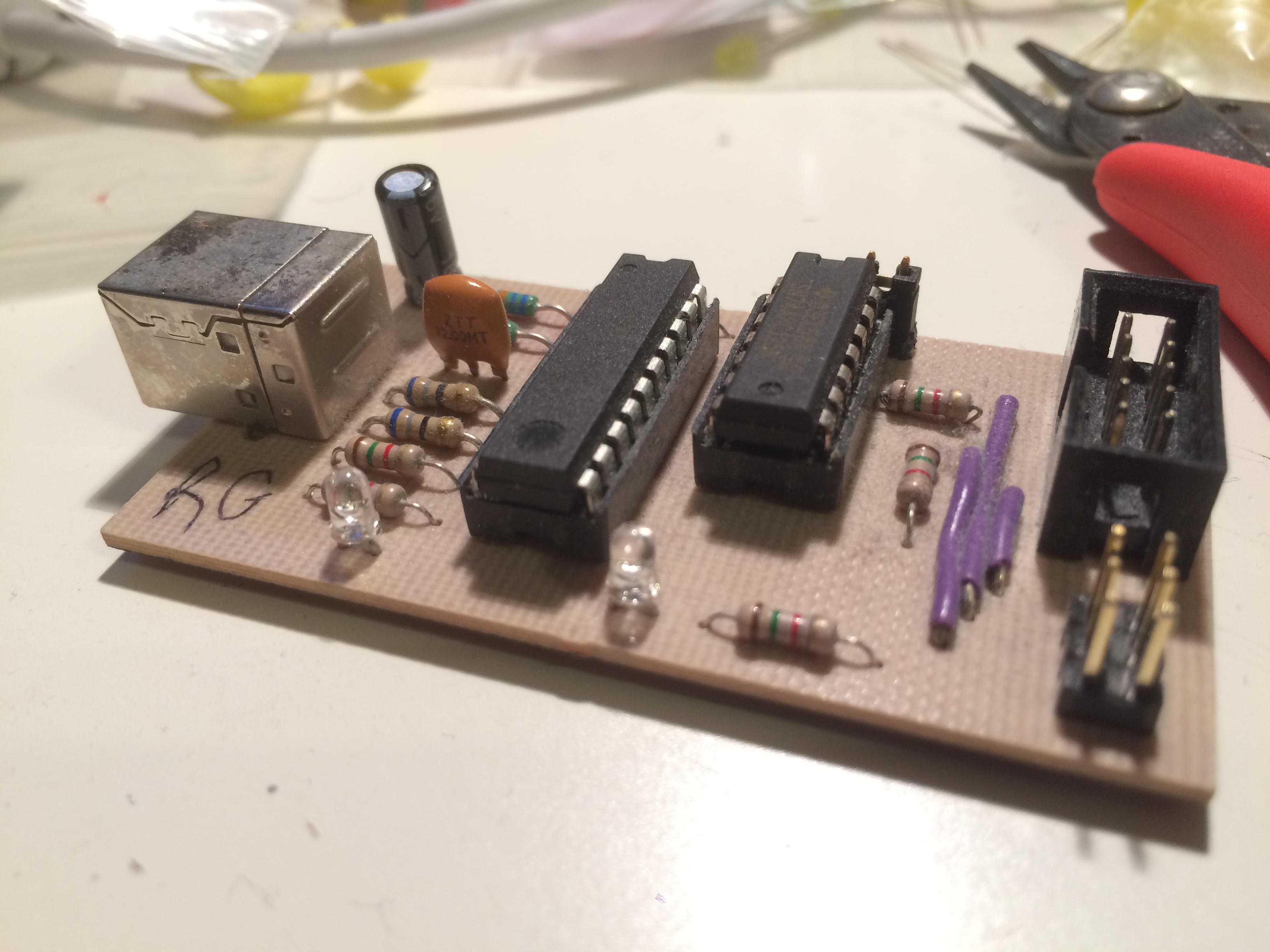
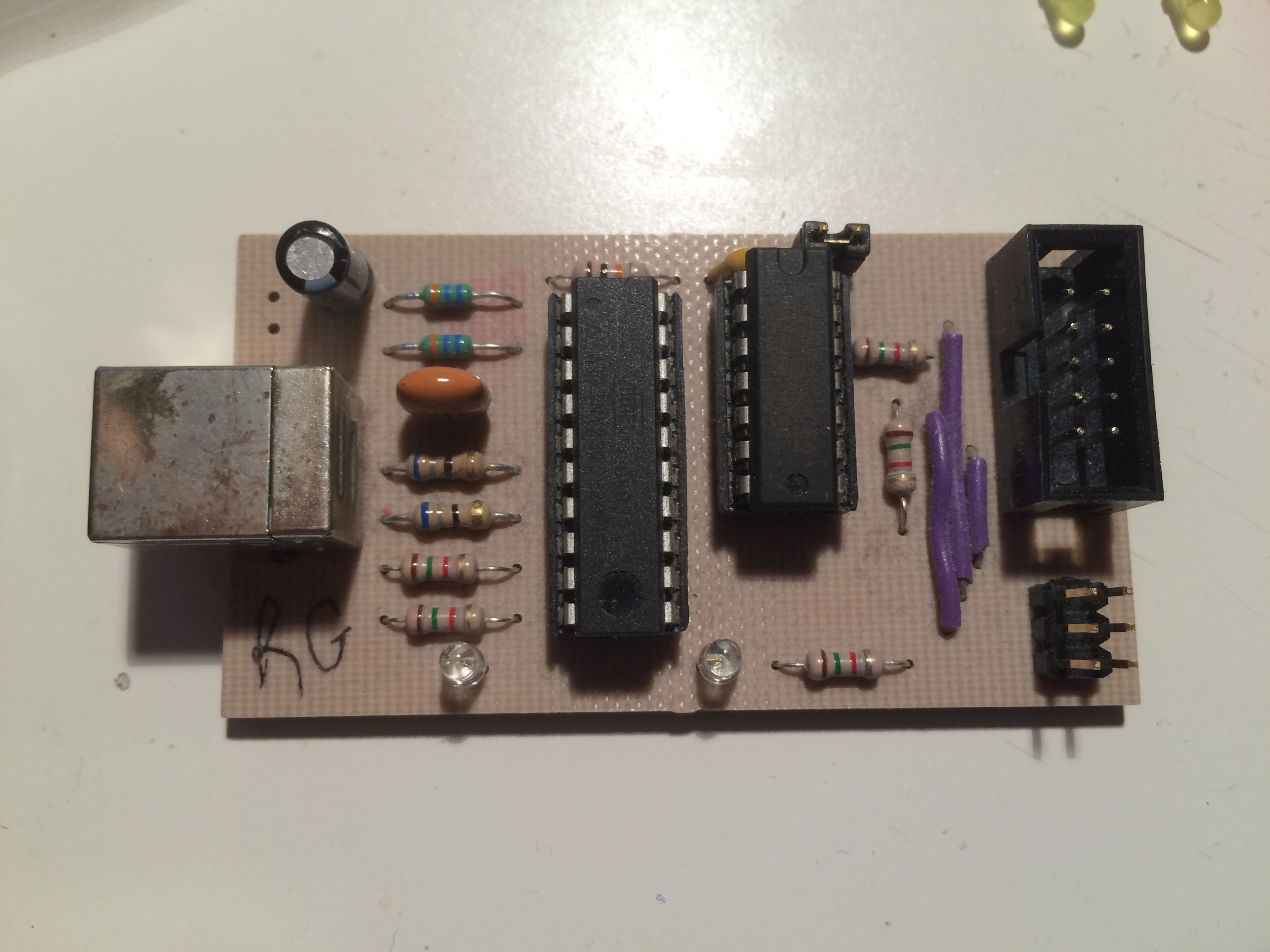
Adafruit has put together good documentation on this programmer, including parts list, assembly instructions, and usage instructions. The only difference between theirs and this one is that this one is the single-sided board. Our GitHub has the EAGLE CAD files for this project, from which you can make the Gerber and Excellon files to build the circuit board.
Note that there are three top-side wires near the programming connectors that need to be added when building this project.
Software setup
Again, consult the Adafruit directions linked above for usage. The biggest problem with building this AVR programmer is that it needs a programmed AVR. The HEX file for programming an ATTiny2313 for this is available from this Adafruit page. You can use an Arduino as an ArduinoISP programmer to program this chip, or get a friend with an AVR programmer to do it for you.
Future improvements
I’m not doing anything further with this project, aside from maybe cleaning up the schematic a bit. The USB implementation used here is pretty messy - it’s software-based, outside of the USB spec, and has some issues with USB 3.0 hosts - so I’d prefer to go with other methods nowadays. Other options are much cheaper now than they used to be.
Conclusion
Another boring project, that won’t be updated in the future. Sorry for that. Tomorrow should be better.
But if you’re looking to build a cheap, fairly reliable AVR programmer at home - and aside from some issues with newer USB ports, mine’s been reliable - this is a decent one.