Mini I2C LCD Backpack: Open Hardware Advent Calendar Day 2
The second project in our Advent Calendar is a quick, simple, and old one - mostly because I had some phone repair issues today that wound up taking more time than originally planned. This project is a small circuit board to put on the back of a character LCD module, to allow it to be controlled over the I2C bus.
Overview
The Mini I2C LCD Backpack is a clone of part of the Adafruit LCD backpack. Theirs works with both I2C and SPI, while this one only uses I2C. This one is also about half the size, and rather than using the standard 1x16 LCD pinout, it uses the 2x8 (or something close to it).
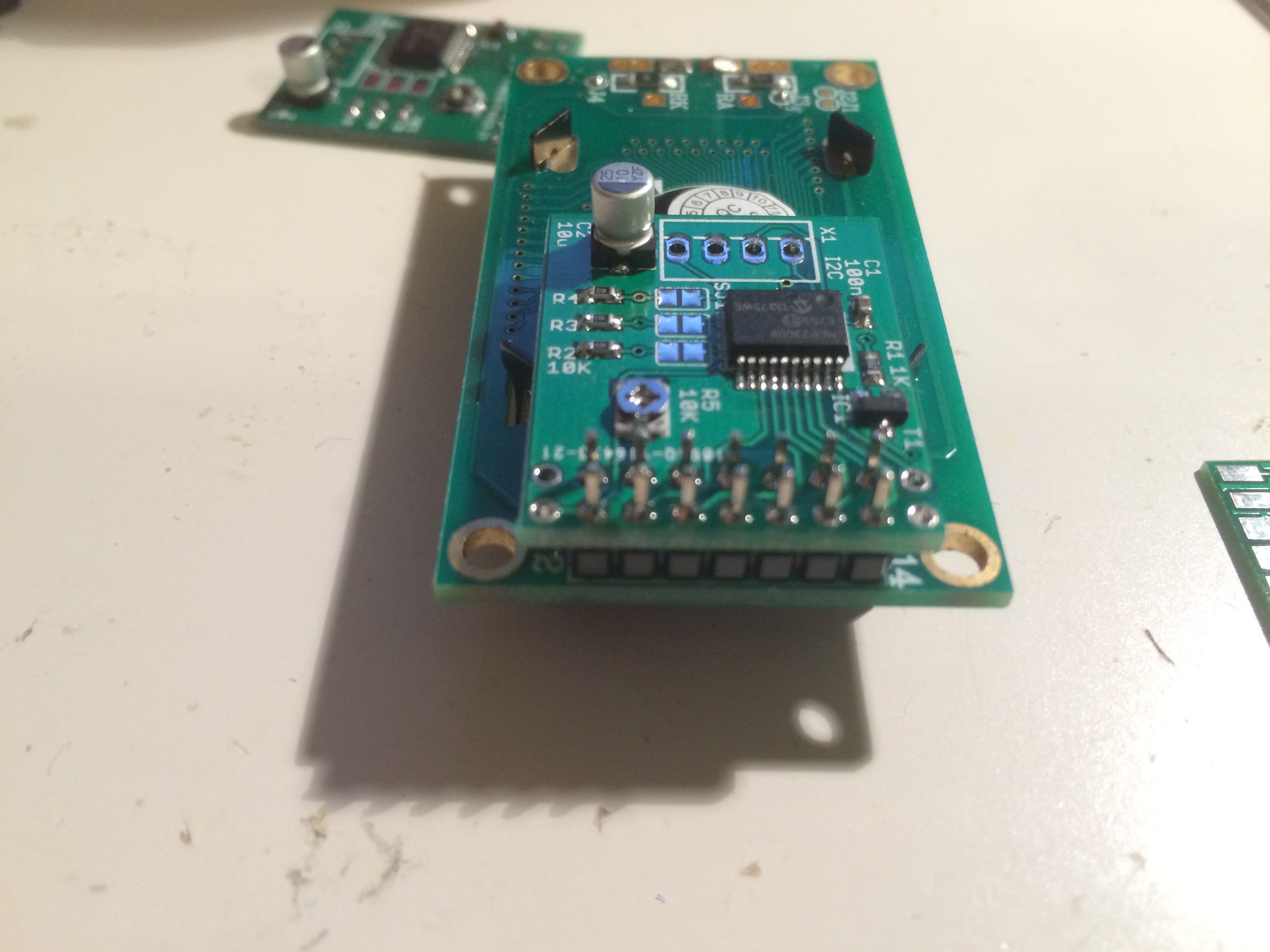
I made this one because I’d picked up a bunch of 8x2 character LCD modules, and wanted to use them on I2C. Doing so means that you can chain a bunch of LCDs or other things off of one microcontroller, and use only two I/O lines to do so. The Adafruit module didn’t fit the pinout of these modules, though, so I designed this. I also had issues with the Adafruit module’s schematic - it was a bit tricky to read, because the data lines aren’t labelled well.
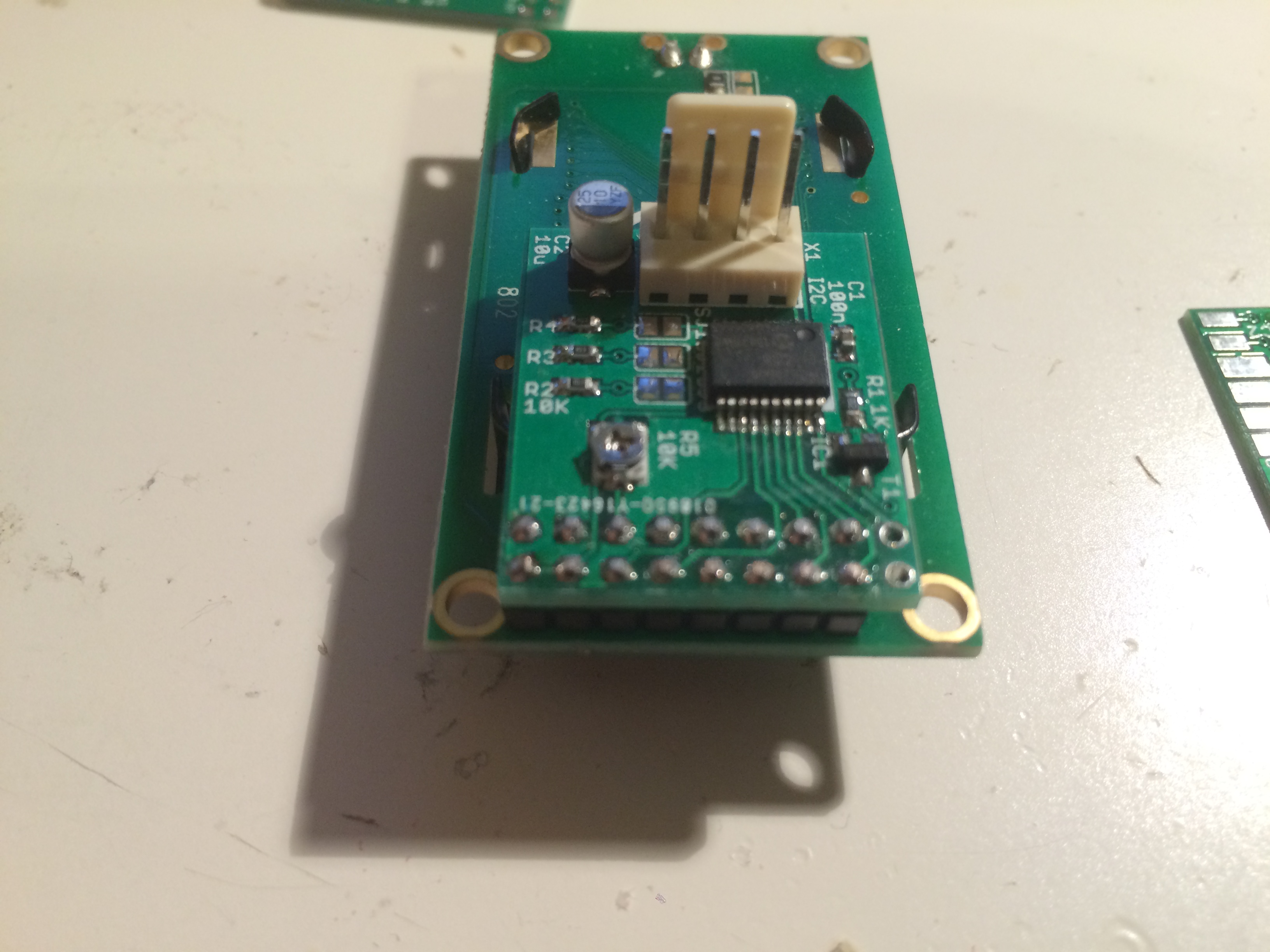
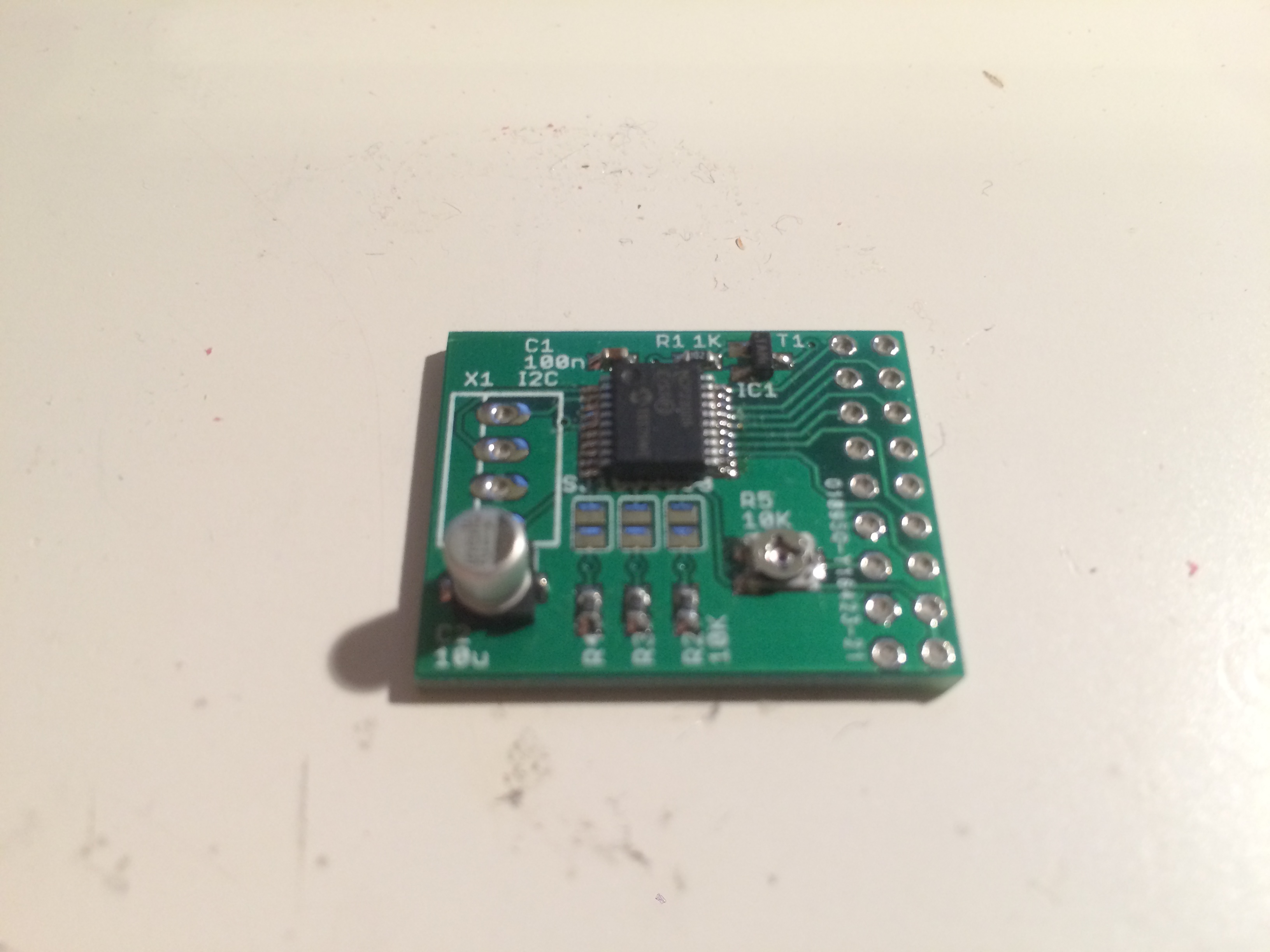
The board is done with the smallest surface mount parts I was comfortable using without magnification equipment, to keep it small - 0603 resistors and capacitors, and the SSOP package of Microchip’s I/O expander.
Parts list
- 1 PCB
- 1 polarized 4 pin header
- 1 MCP23008 in SSOP package
- 4 10K 0603 package resistors
- 1 100nF 0603 package capacitor
- 1 10uF B-package electrolytic capacitor
- 1 10K potentiometer
- 1 MMBT3904 transistor
- Optional: 0.100” socket header
Building the hardware
This one’s a mostly surface mount job - the parts are labelled on the board, so it should be easy to go together.
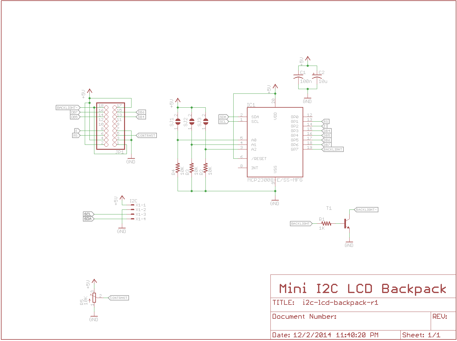
You can download the schematic and PCB files (including Gerber and Excellon data) from GitHub. Boards were ordered from Seeedstudio’s Fusion PCB service for this project.
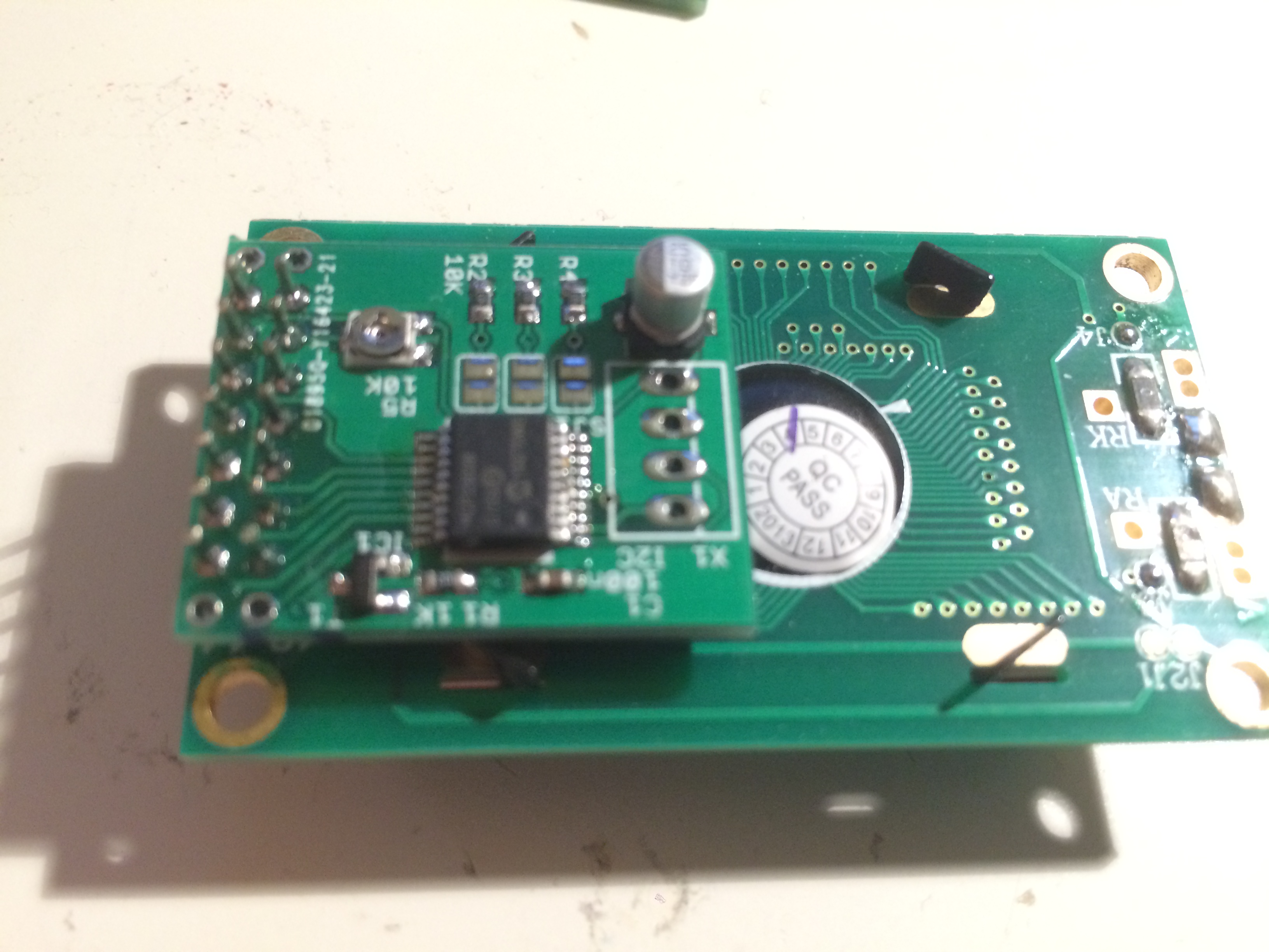
The tricky bit comes in attaching it to the LCD. I did something weird with the pinout on this one - most LCDs with the 2x8 pinout have the backlight on pins 15 and 16. A few of the modules I had, however, had the backlight on pins 1 and 2. So that the same board would work on both styles, I used a 2x9 connector, and put the backlight on both ends. This way:
- If you have the standard pinout, you line up pin 1 on the LCD with pin 3 on the board
- If you have the weird pinout, you line up pin 1 on the LCD with pin 1 on the board
- If you have no backlight pins at all (a 2x7 connector), you line up pin 1 on the LCD with pin 3 on the board.
You can add a set of header pins on the LCD, and put sockets on the backpack board, or just use pins to solder the two together permanently.
Software setup
I don’t provide any software for this one - you can use Adafruit’s modified LiquidCrystal library or use the LiquidTWI library to drive it.
Note that you can connect up to 8 devices based on the MCP23008 to one I2C bus (such as this board) - use the address solder jumpers to configure the address for each board. Completing a jumper on this board sets that address bit to 1.
Future improvements
I don’t think there are much in the way of future improvements for this project - it’s really a building block for making other projects. I used it in my New Year’s Ball Drop project last year, for example.
Conclusion
Again, a simple project - and an adaptation of another one, too. Don’t worry, more exciting things are afoot.