Photobooth Button: Open Hardware Advent Calendar Day 18
Still playing catch up, our next project is for those building a photobooth: a button to trigger it.
Overview
Photobooths are incredibly popular for weddings and other events these days, but are also incredibly expensive. Building one yourself is definitely an option, especially if you already have a decent camera and a computer you can dedicate to it. But wiring up a nice button takes some effort.


What we’ve come up with here is just such a button, using the USB Wildcard board. It fades the LED in button on and off to attract attention, and when pressed, simulates hitting the spacebar to trigger photo taking.
Hardware
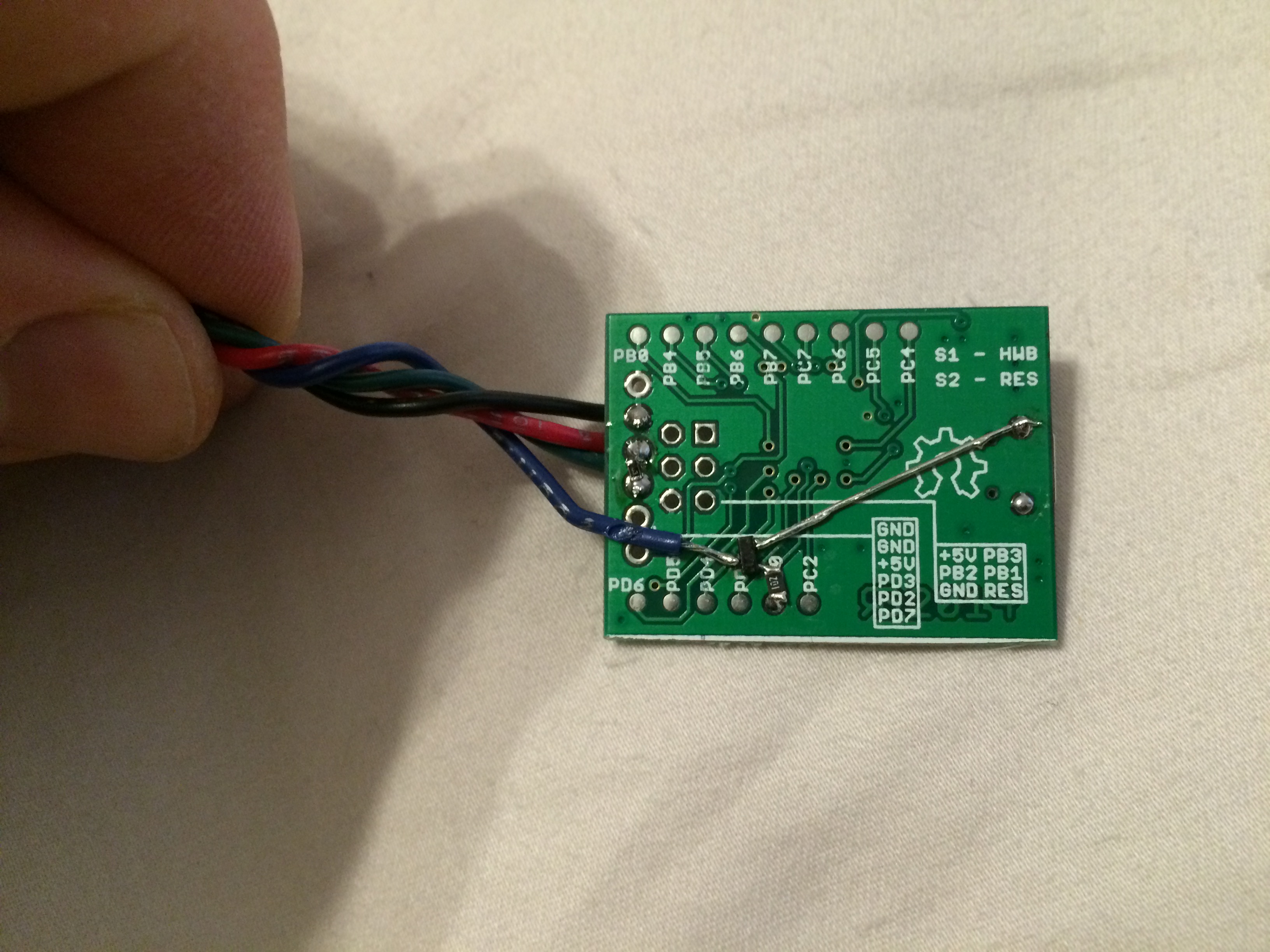
This is another one based on the USB Wildcard. It uses that along with a few other components to drive the LED and read the button.
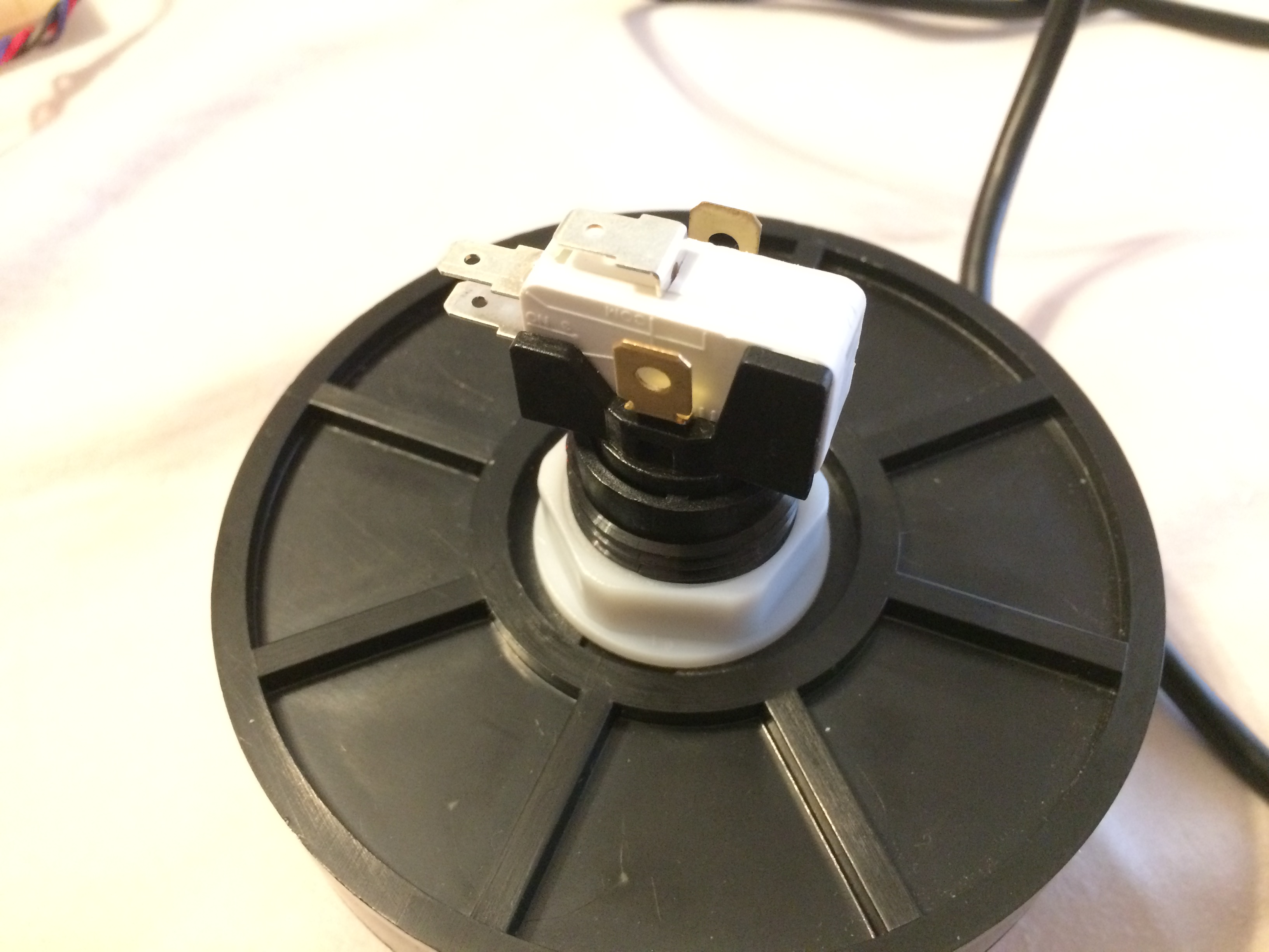
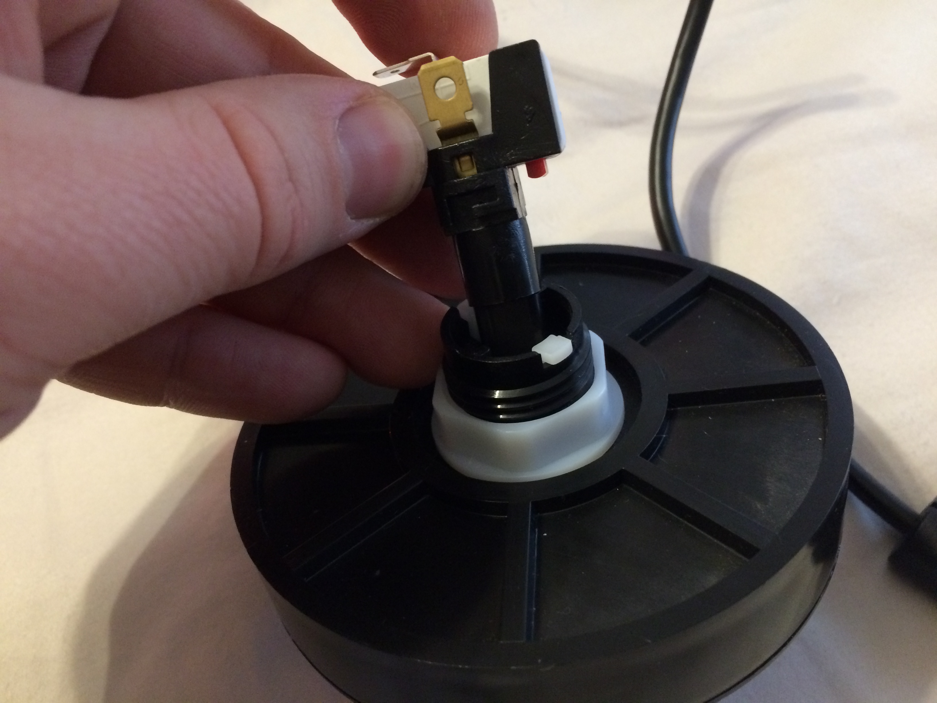
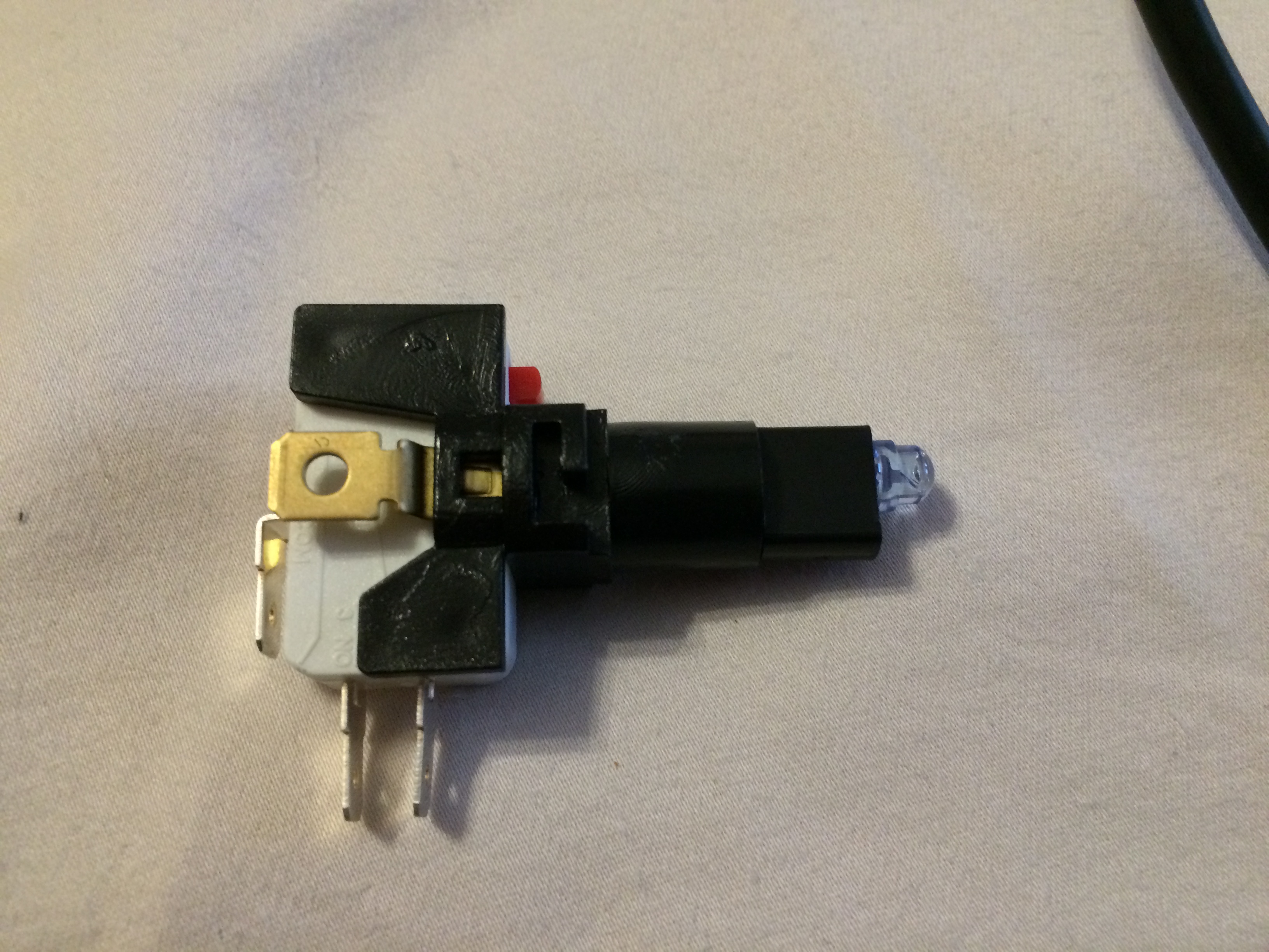
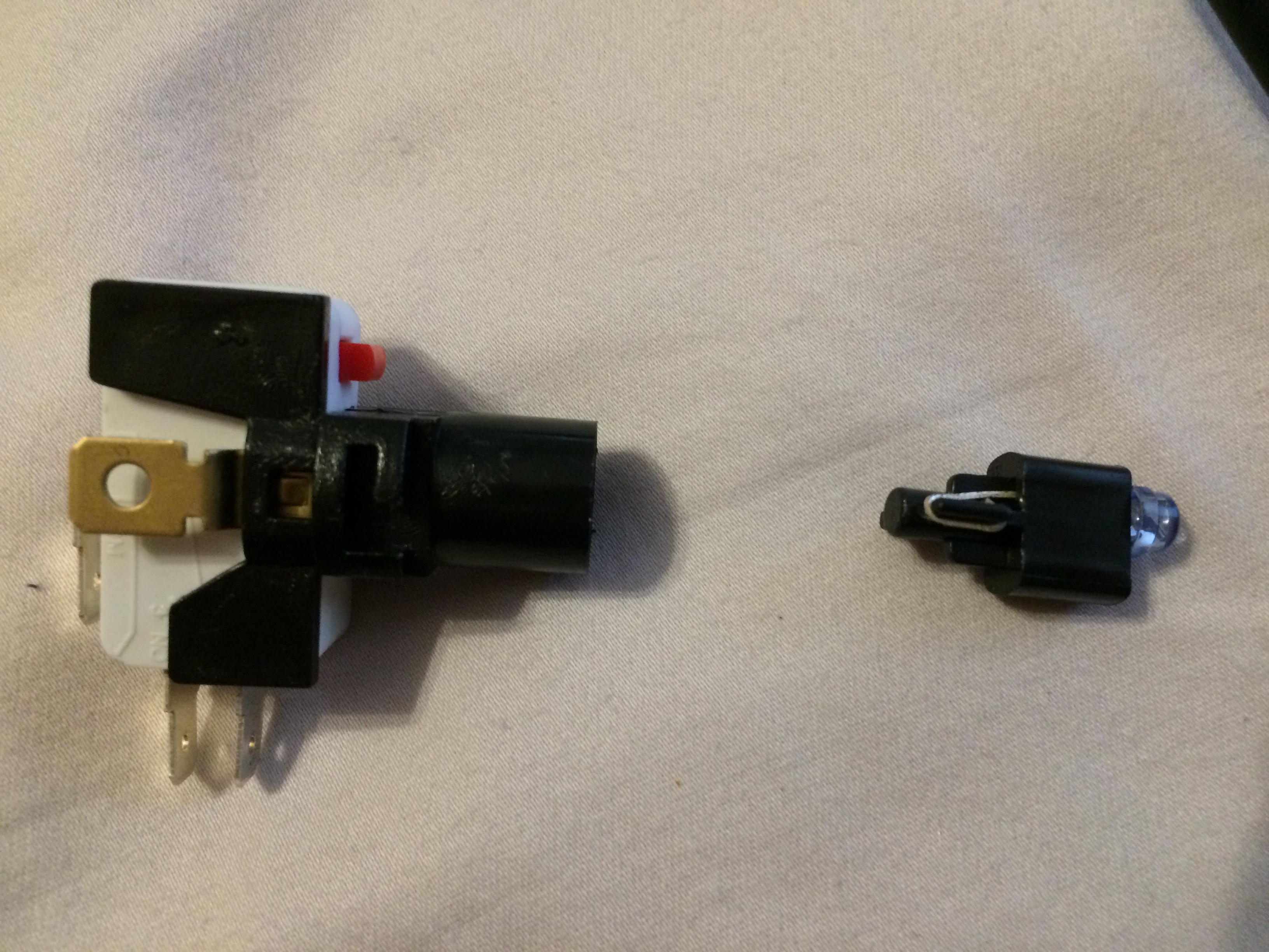
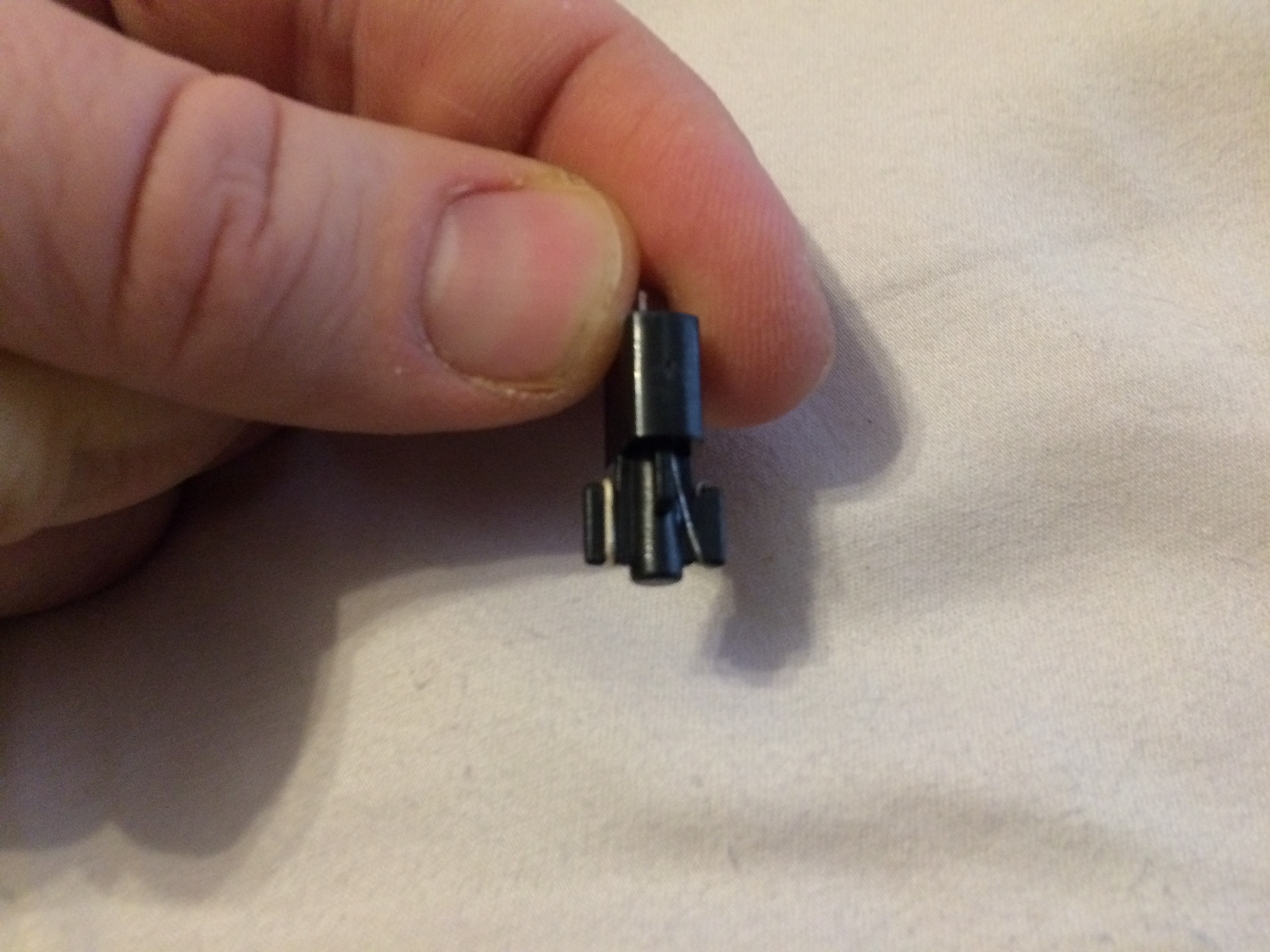
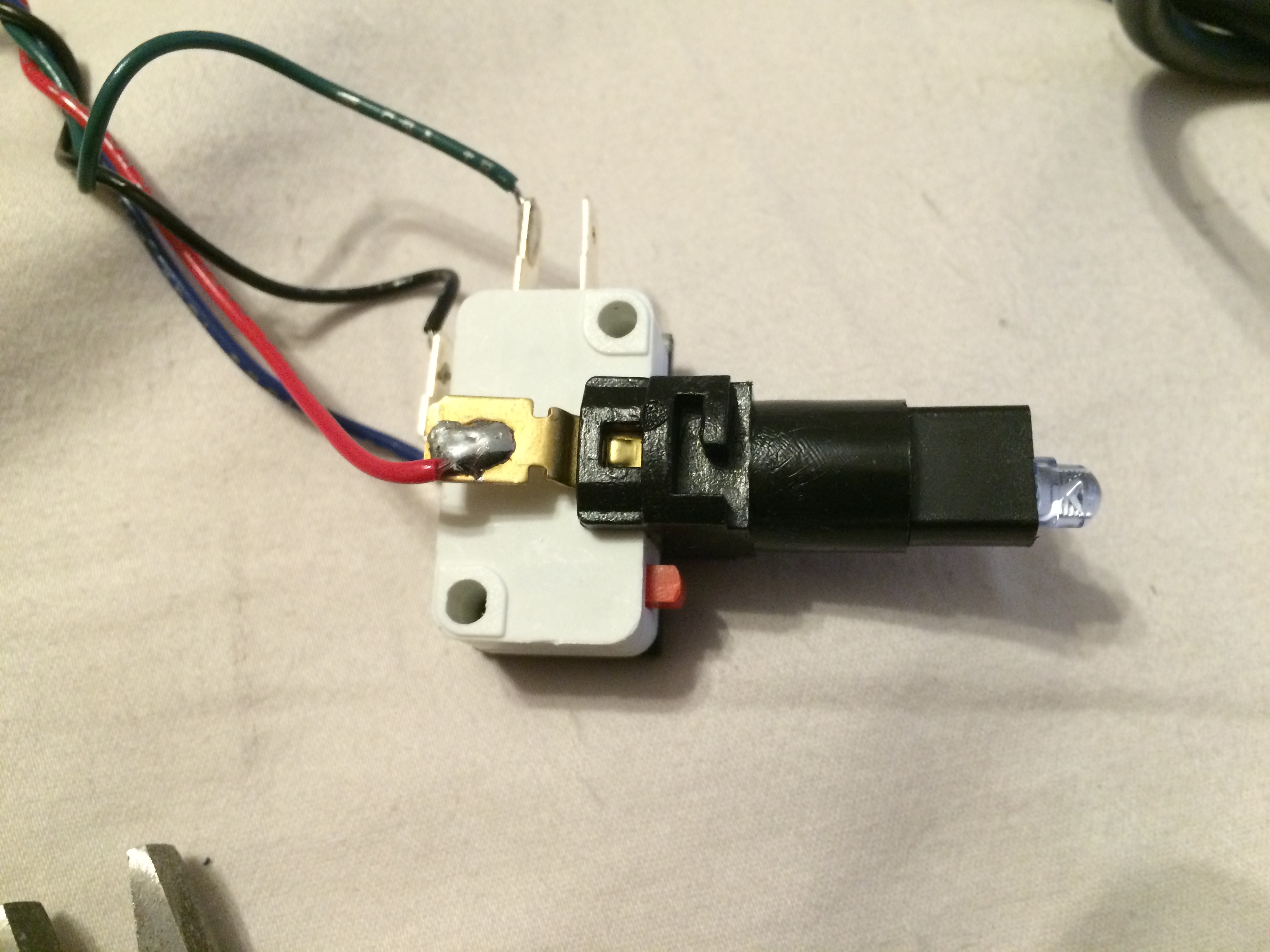
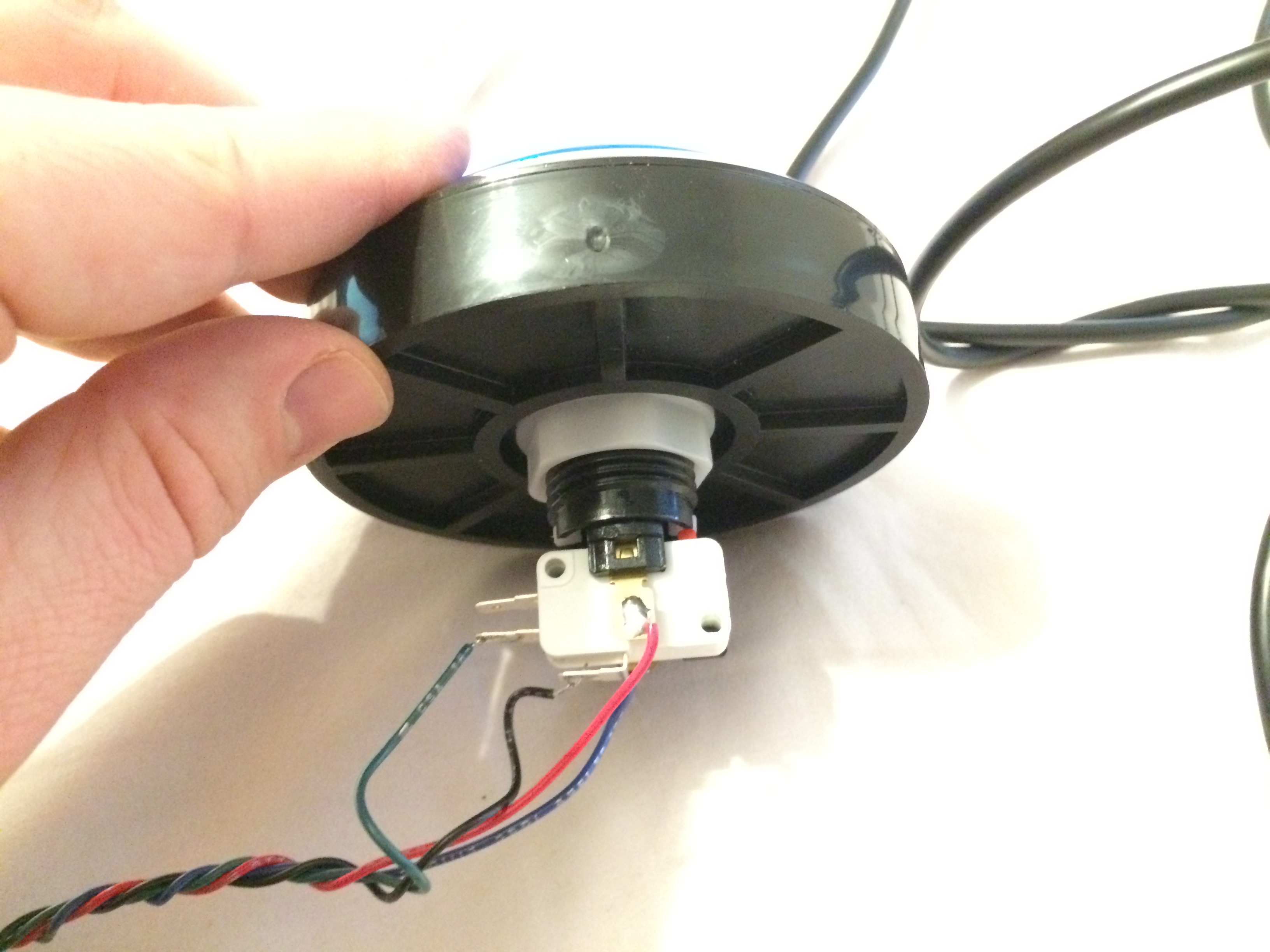
I used a SparkFun Big Dome Button, which needs a modification to work properly. If you try to run the LED in the button on 5V, it will be dim - it’s set up to use 12V, so the resistor is much too large for 5V operation. Refer to the photos above for how to disassemble it, but you basically remove the switch assembly by twisting it, and then pull out the LED assembly from the top of that. Unwind the leads from the plastic frame, and you can pull the LED and resistor out of the assembly. Replace the resistor with a 100 ohm unit, and reassemble.
The following is a very rough schematic of the button:
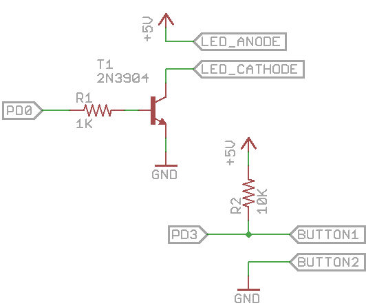
So you’ve got PD0 of the USB Wildcard to a 1K resistor, and that to the base of a 2N3904 transistor. Emitter of that transistor to Ground, and Collector of it to the cathode side of the LED in the button. Anode of the LED to +5V, and then one side of the button to Ground. The other side of the button goes to PD3, and a 10K pull up resistor from PD3 to +5V.
Software
This requires the same Arduino setup as yesterday’s project, so follow the instructions there. Then, you can download the software from the GitHub project for this project. Load the software and you should be good to go.
Here’s a video of it in action:
For this video, I used Sparkbooth but you can substitute whatever you like.
Future plans
About the only thing I’d like to add to the current version of this project is some debouncing for the button, but given the delays used to lock out the button after pressing it once, it’s probably not a big issue. I’d also like to look at an even cheaper version using one of Microchip’s new USB PICs - that one would require a cheap microcontroller and a couple resistors and capacitors.
Conclusion
This is an easy-to-build photo booth button that’s still easy to customize, thanks to the use of the Arduino software to implement it. I hope someone finds it useful.