NESVerter
Introduction
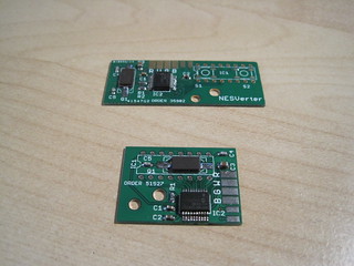
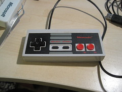
The NESVerter is a conversion board to make an original NES controller into a USB gamepad. It originally came about after I made one based on this one over on raphnet.net for my friend Kat. I wanted to try making a PIC-based version that would fit inside an NES controller without modification to the case. This is the result.
The NESVerter is a small PIC18F14K50-based board that solders into an NES controller in place of the standard 4021 shift register. It requires removing that part. For more on how the NES controller works, visit here.
Hardware
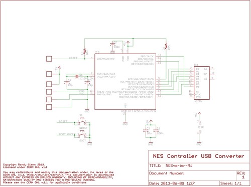
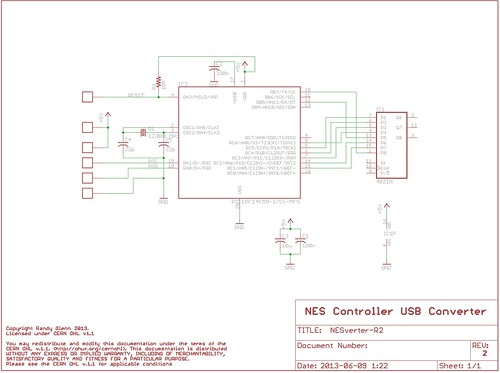
There are two versions of the hardware, mostly the same. Version 1 is a slightly larger board, with a reset and a bootloader button so you can download new code to the board. Due to a miscalculation on my part, Version 1 requires filing down part of the case. Version 2 is smaller (thus no filing) and loses the buttons in favour of using the controller’s buttons on power up to activate the bootloader.
The schematics are as follows:
This is a very, very basic USB PIC setup. There are some pads for ICSP and USB connections, a couple of capacitors for the PIC, a crystal and load caps, pullup resistor on reset, and the 330nF capacitor on the VUSB pin. The 4021 is only used in the schematic as a footprint - it’s actually populated as pins connecting the board in place of the removed 4021 in the NES controller. Pullup / pulldown resistors on the inputs aren’t required, as they’re in place on the controller PCB (as printed-on carbon).
Firmware
The firmware can be downloaded at our Bitbucket site here. It’s based on JALv2 with JALLIB. HEX files are also included. The first versions were based on Microchip USB stack examples, but licensing issues with those led me down the JAL route, which actually turned out well.
There are actually two parts to the firmware. The first is the USB HID bootloader, which allows you to download updated code to the controller without taking it apart and breaking out the PICKit2. There are two versions - one for the V1 hardware and one for the V2. The V1 one uses the buttons on the PCB, while the V2 requires that you hold down the A and B buttons on the controller while plugging it in to enter the bootloader. I think the V2 one will work on the V1 hardware, so just use that. The bootloader gets loaded on via the ICSP board and something like a PICKit2.
The second part of the firmware is the actual gamepad firmware, which you load on via the bootloader. This is a very basic USB Gamepad firmware. I copied the USB descriptor from raphnet’s version, and much of the rest of the code comes from this JALLIB sample. All it really does is check which buttons are pushed, and sets the appropriate bits in the USB HID report for those buttons. That’s it. The code is documented if you want to have a look.
Building it
The board is all-SMD, and fairly tiny stuff too. I’m only providing instructions and a parts list for Version 2, as I don’t recommend building Version 1. You’ll need the following parts:
| Device | Quantity | Parts on board | Digi-key part number |
|---|---|---|---|
| 10K 0603 resistor | 1 | R1 | 311-10KGRCT-ND |
| 10uF 0805 capacitor | 1 | C3 | 445-1371-1-ND |
| 12.000 MHz Crystal, 5x3.2mm | 1 | Q1 | 535-10875-1-ND |
| 22pF 0603 capacitor | 2 | C4, C5 | 445-1273-1-ND |
| 100nF 0603 capacitor | 1 | C1 | 311-1343-1-ND |
| 330nF 0603 capacitor | 1 | C2 | 445-5142-1-ND |
| PIC18F14K50, SSOP package | 1 | IC2 | PIC18F14K50-I/SS-ND |
Note the thickness of the PCB - using standard 1.6mm PCBs is a bad idea here. Pay a little extra for thin, if you have to - I went with 0.8mm.
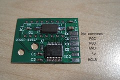
I won’t cover how to build the board - if you’re experienced with surface-mount soldering, odds are you can figure out where stuff goes based on the parts list above and the silkscreen on the board. You will need to burn the bootloader to the board, however. For that, I use a PICKit2 with a cable and pogopins. The same pads that are used for USB can be used for ICSP to load the bootloader - connection is as follows:
Here’s how to assemble the controller:
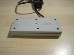
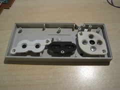
- Get an NES controller
- Open the controller, and remove the board from the case
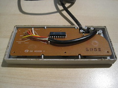
- Desolder the cable
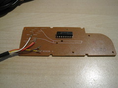
- Desolder the 4021 chip
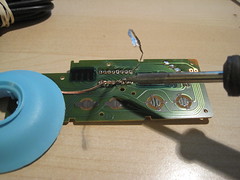
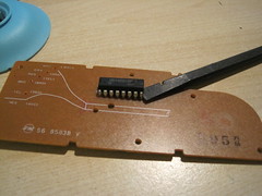
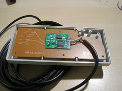
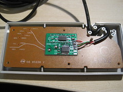
- Line up the NESVerter over the IC holes
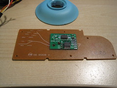
- Thread small-gauge wire through the holes, and solder on both sides. Then, clip the wires.
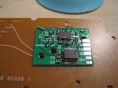
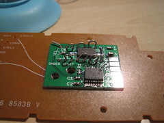
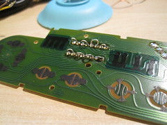
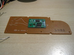
- Cut the end off the USB cable (the PROPER end - not the type A plug!). Strip and tin the wires.
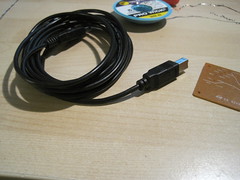
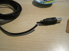
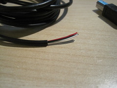
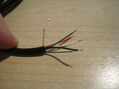
- Solder the wires to the PCB. The pads are indicated with the colour of the wire (G = Green, W = White, R = Red, B = Black) that attaches to them.
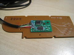
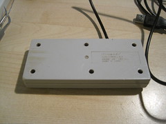
- Route the USB cable, and reassemble the controller
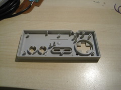
 </ol>
</ol>
- Open the program
- Hold down the A and B buttons on the controller (for the V2 bootloader) or press the bootloader button (for the V1 bootloader) and plug in the controller
- The app should indicate that the device was found.
- Click the Open button, and open the nesverter.hex file from the code-gamepad directory in the source code download
- Click the Erase/Program/Verify button to download the code
- When the app tells you, unplug the controller and plug it back in.

