Light Paintbrush: Open Hardware Advent Calendar Day 8
Today’s project is a really fun one: a Trinket-based LED paintbrush for light painting.
Overview
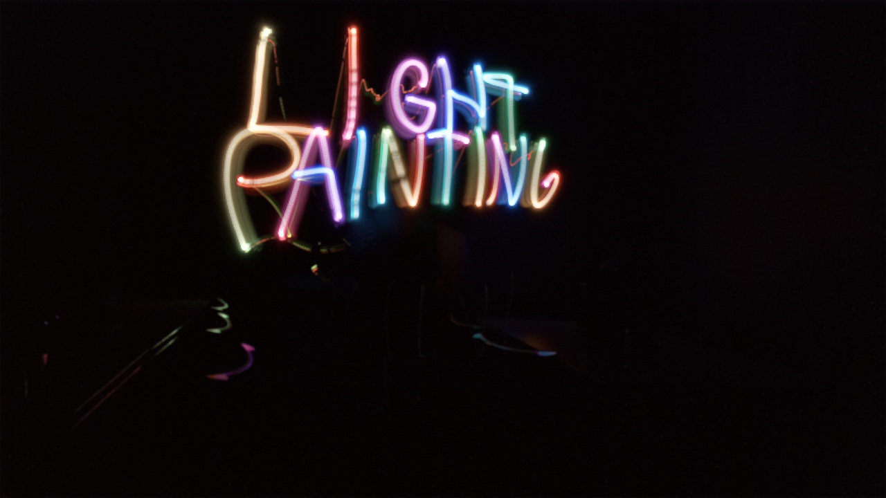
The Light Paintbrush lets you do light painting in different colours. Light painting is a technique where you take a long-exposure photo in a dark area while moving a light source of some sort, and you wind up drawing with the light source.
The Light Paintbrush uses an RGB NeoPixel LED, a dial, and three buttons to let you choose the colour you draw with, and paint your heart out. The buttons select the mode, and the dial has different functions based on the mode.
It has three modes:
- Paint mode - where the dial selects the colour, and the colour is shown at full brightness
- Preview mode - where the dial selects the colour, and the colour is shown at half brightness. This is to let you see what colour you’re going to draw with, without affecting the picture you’re drawing as much.
- Colour wheel mode - where the colour automatically fades from one to the next, and the dial chooses the speed that it changes at.
To actually take the picture, you can use any camera or app that supports long exposure or bulb exposure. I used an app called SlowShutter on my iPhone, and set it for Light Trails, and Unlimited Exposure. That way, I set when it should start the exposure, and when it ends, by tapping a button on the screen. You can also do timed exposure. You’ll have to find out what works with your phone or camera.
Parts list
Three buttons One 5V Adafruit Trinket One 8mm through-hole NeoPixel Three 10K ohm resistors One 100 ohm resistor One 10K potentiometer One 3xAAA holder with switch One Adafruit 1/4 size prototyping board
Hardware setup
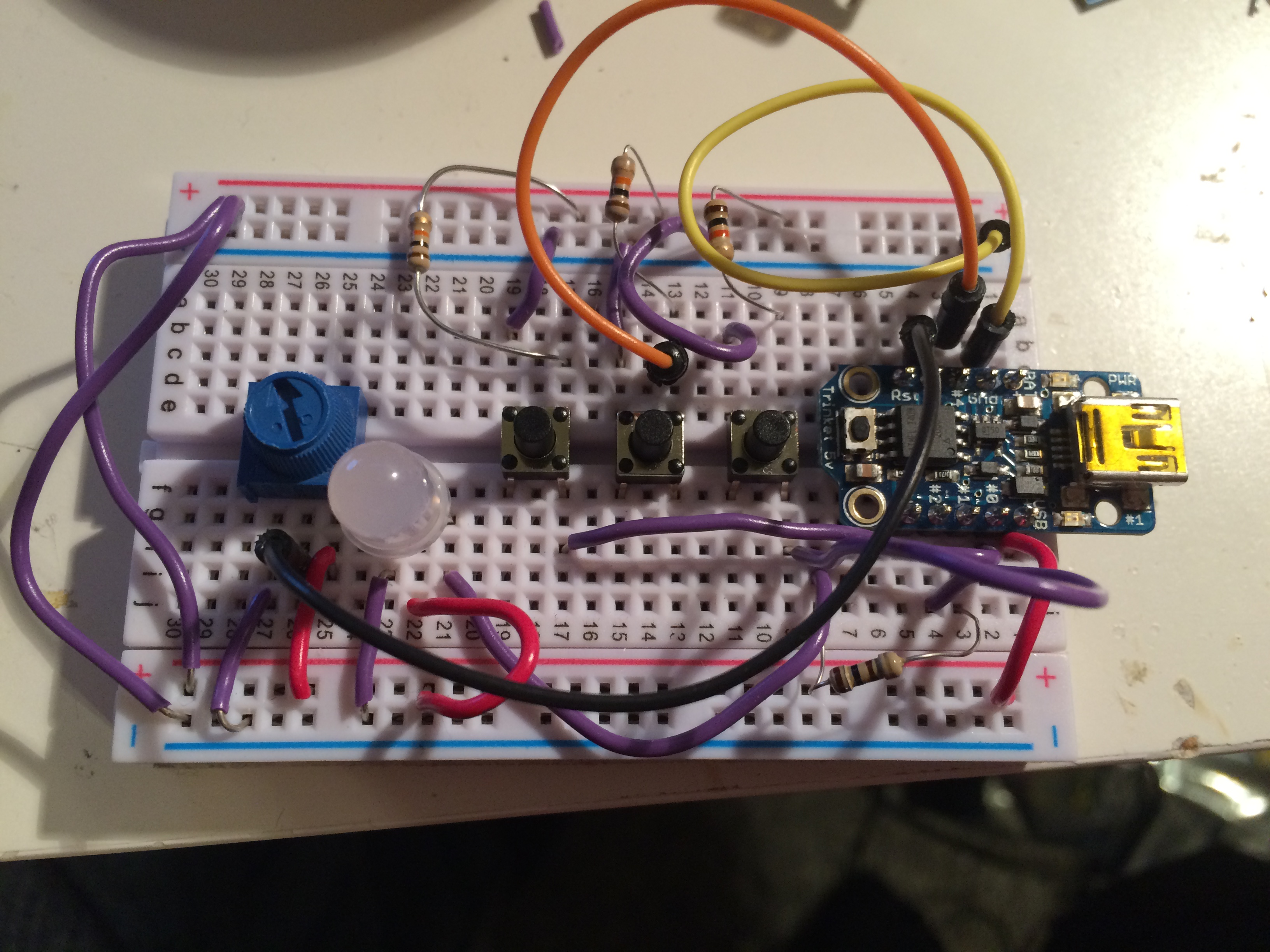
The hardware setup is pretty simple - three buttons to ground (Paint on pin #0, Preview on pin #4, Colour whele on pin #2), each with a 10K pull-up resistor, a 100 ohm resistor between the Trinket (pin #1) and the data in pin of the NeoPixel, and the potentiometer connected from 5V to Ground, with the wiper connected to pin #3 on the Trinket. The Fritzing diagram below shows the setup on a breadboard.

The Fritzing file and Arduino code can be downloaded from our GitHub.
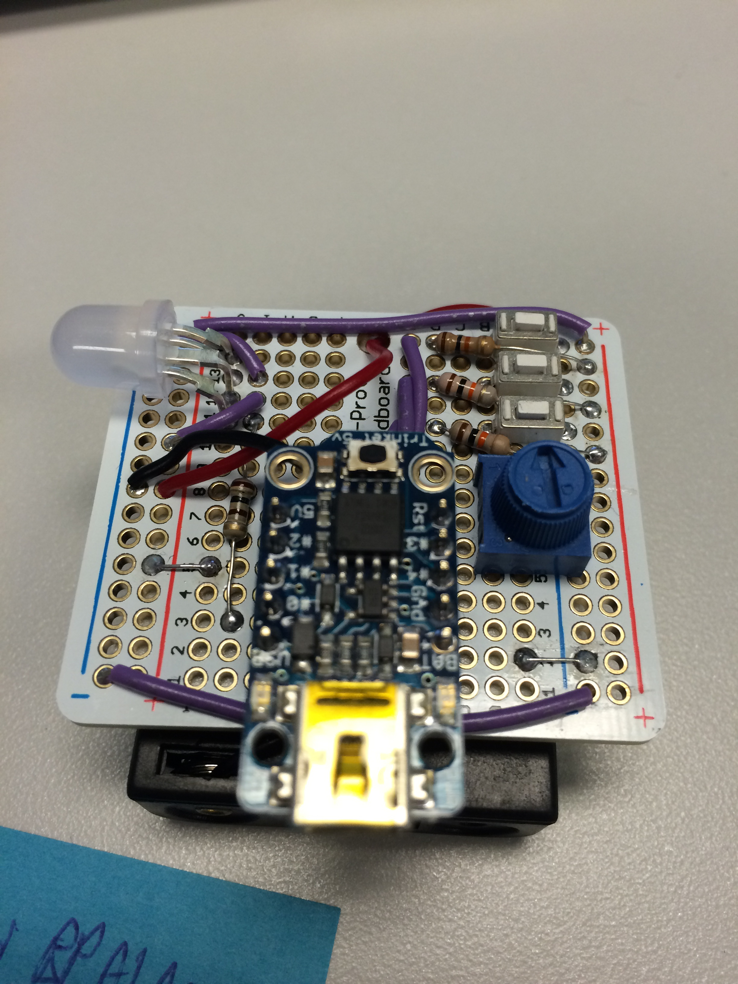
I prototyped it on a breadboard, and eventually transferred it to a prototyping board to be more permanent. Photos can be seen in the gallery above.
Software setup
First, you’ll need the Arduino software on your computer set up to use the Trinket. Also, you’ll need to set up your Arduino software on your computer to use the Adafruit NeoPixel library. The Arduino sketch for this project can be downloaded from our GitHub. Load the code into your Trinket as per Adafruit’s instructions.
Note that your Trinket cannot be connected to the rest of the circuit when you’re loading code to it, as we’re using the pins that it uses for USB for other things. So unplug your Trinket, connect it to USB, load the code onto it, unplug it from USB, and put it back in the circuit.
The software does some interesting things - it does not, for example, work directly with Red, Green and Blue colours, as a lot of systems do, but rather manipulates them as HSV - Hue, Saturation and Value. This lets us maintain a consistent brightness between colours, and fade between them much more cleanly. Darcy White has a good article about why you want to use HSV/HSI, and about colour mixing in general. I borrowed some code from Kasper Kamperman to do the conversion on the Trinket.
Future plans
This project is TONS OF FUN to use, but there are a few things to improve. I’d like to make the overall form factor a little easier to work with, and maybe make the power source (currently 3 AAAs) a bit smaller. Also, the 10K resistor - which is what I had, and had a nice knob on it - is too close to the internal impedance of the ADC in the Trinket’s microcontroller. What this means is that microcontroller heavily affects the reading of the dial, and we get non-linear behaviour. There’s an easy fix for that - use a 500 ohm or 1K ohm potentiometer instead - but I don’t have one on me.
I do plan to make a Version 2 of this project, so watch this space. Maybe some colour preset buttons for faster switching?
Conclusion
This was a lot of fun to build, and a ton of fun to test - I really hope you try it out yourself.