Ottawa Mini Maker Faire 2014: Badge Edition
The weekend before last in Ottawa (August 16-17, 2014) was the fourth annual Ottawa Mini Maker Faire. Mike, Chris and I exhibited the pinball machine - more on that in a trip report later. For this Faire, however, I worked with the organizers on making some special LED name badges for the Makers. This article serves as documentation of that project.
Timeline
Britta Evans-Fenton, one of the Faire’s organizers, came out to Mini Maker Faire Montreal (June 7-8, 2014 - again, trip report pending), so I got to talk to her there about this year’s Ottawa Faire. On the train trip back home to Toronto, I got the idea of having some sort of PCB name tag for the participants. I toyed with the concept for a while, and eventually came up with an idea, which I sent to Britta. This was June 18, at this point.
We promptly both got busy, it seems - I dropped the project for a bit due to other priorities (such as Maker Faire Detroit preparations - once again, trip report pending). In the mean time, however, I somehow had the foresight to order sufficient dirt-cheap battery holders and power switches from Aliexpress. Power switches were something I wanted from the get go - we want the batteries to last all weekend in these things, and a good way to do that is to make sure that the light can be turned off at night, when you aren’t wearing it.
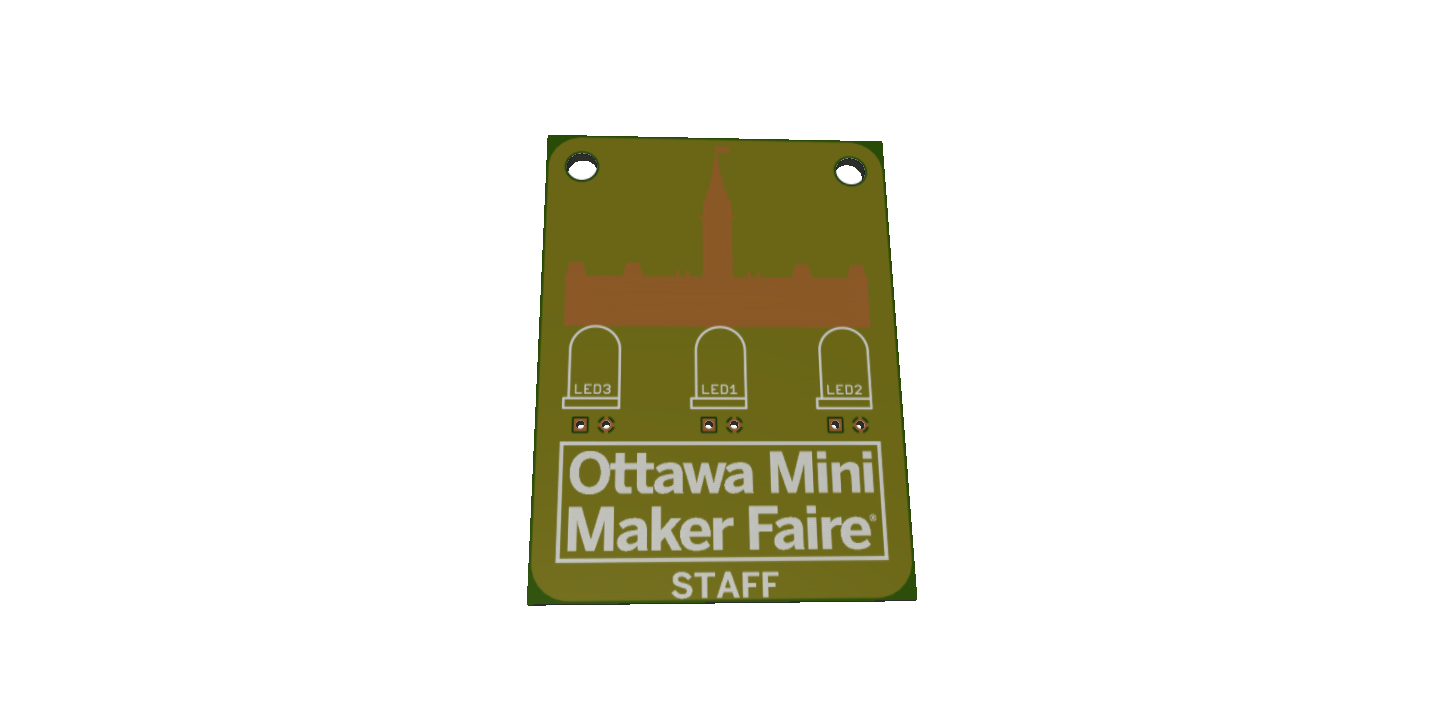
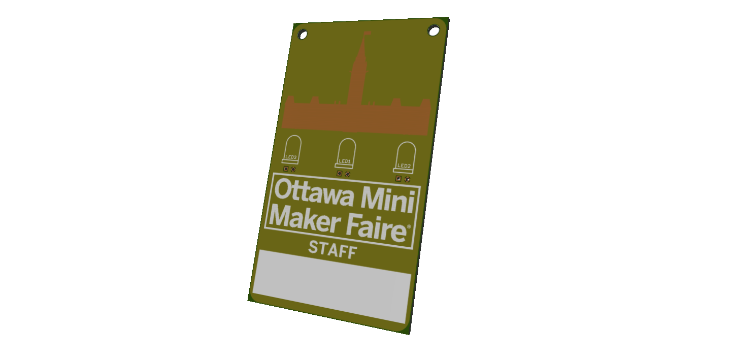
Around the first week of July, we started trading ideas back and forth, and I went back to the design. The idea at this point was for a silhouette for Centre Block illuminated by some LEDs, the Mini Maker Faire Logo, some silkscreened text of the badge type (Staff, Volunteer, Maker, Sponsor), and a large silkscreened area for the wearer’s name.
On July 15, I did some 3D renders, and send off for prototypes, in two sizes - a mini one that would be best with a pin backing, and a larger one that would be best for a lanyard.
The boards came back on July 23rd - I went for express shipping - and while we were waiting for them to arrive, Britta and I came up with a slightly different plan, to cut down on costs:
- Use the lanyard-sized boards
- One kind of board - no silkscreen text for badge type. This meant we were ordering more of one kind of board, so the quantity discounts were higher, and we only paid one setup fee.
- Larger area for writing
- Different LEDs for the different badge types - colour-fade for sponsors, white for staff, blue for Makers
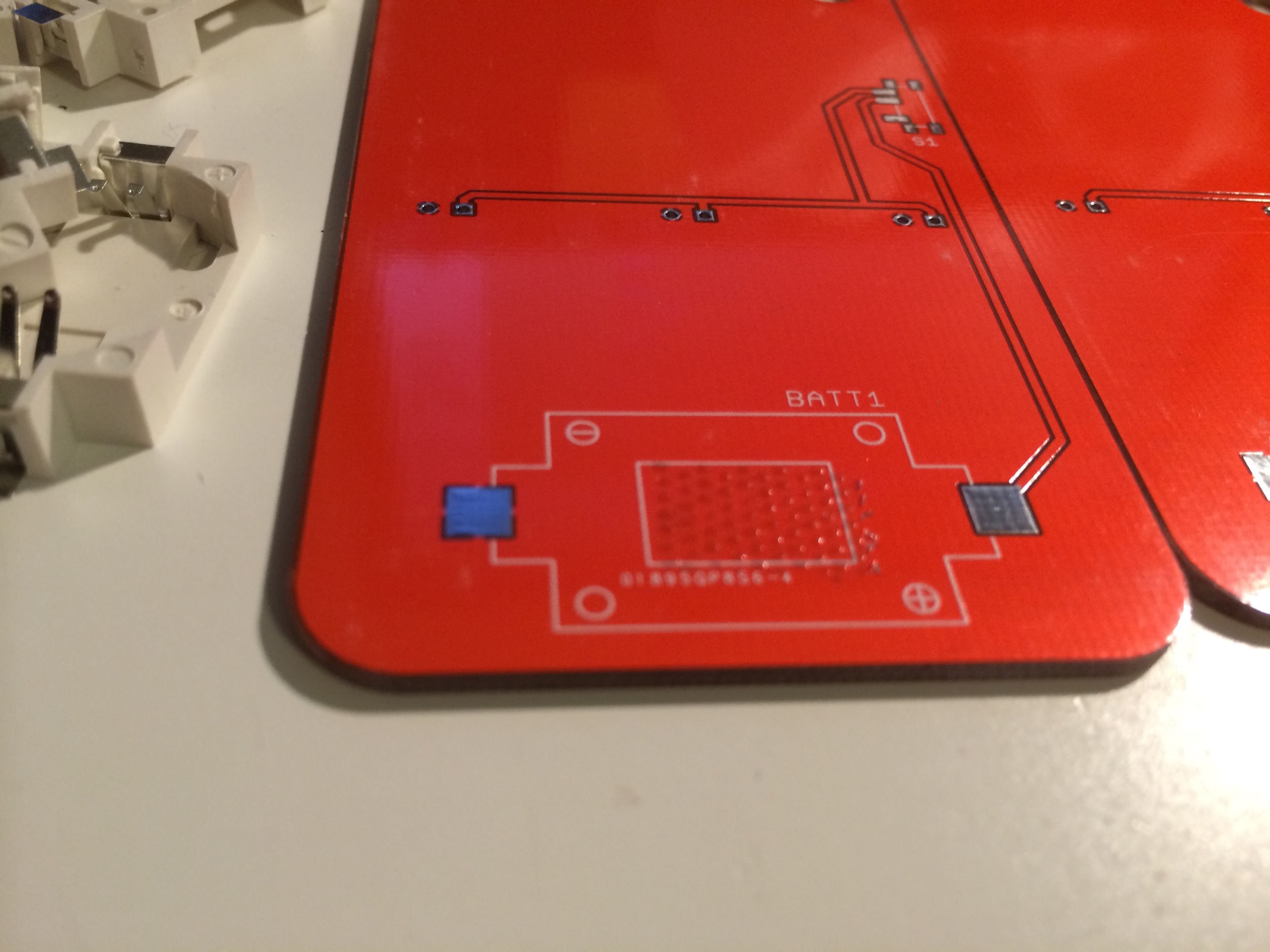
- Red PCBs for all
So when the boards did arrive, we already had a few changes ready to be done.
I quickly populated one when I got the boards, and fired a video up to Ottawa to demonstrate it.
After looking at the prototype boards, I also decided that the lanyard holes needed to be bigger - about a quarter inch / 6.35mm. I made the changes and sent them off on July 29, once the Detroit Faire was done. They shipped out on August 4, and arrived on August 7. From the 8th to the 14th, I started assembly at home, first putting the battery holders and switches on each board, then starting to add LEDs as numbers came in for sponsors, Makers, etc.
During this time I also did some battery life testing, 4 hours at a time. I was a bit worried about power draw given the lack of current-limiting resistors in the design. The Blue ones passed with flying colours - after 16 hours of on time, they were still usable. The colour fade ones did not - Blue went out after about 2 hours, and Green went out after about 6, leaving only Red working at the 16 hour mark. Because of this, the Partner badges with colour fade LEDs got 150 ohm resistors added by way of an x-acto knife and careful soldering.
Around the 14th, we remembered that we needed lanyards for these. I found some cotton and nylon cord at Wal-mart that fit the bill - 3’ sections worked perfectly for a lanyard (it came as 45’ lengths, hence the US Customary units). This was more expensive than I would have liked, but we were time-constrained. Wal-mart ran out of cotton cord, so I had to use Nylon as well, which required sealing to prevent fraying. This was done with fire, which had predictable results.
Apparently honey can be used to treat burns. I had no idea.
Badges were ready a few hours before we had to leave for Ottawa. Our departure was delayed a bit by car trouble, so Britta and I had to coordinate the transfer of badges. I had intended to deliver them the night before, but we got to our hotel at 3:30 AM, so that was out of the question, and us arriving at the Faire the moment it opened at 8:00 AM was… unlikely. So they were left with the front desk at the hotel.
From there, Britta and company handled distribution to each of the Makers, and there was much rejoicing and jubilation.
The Design
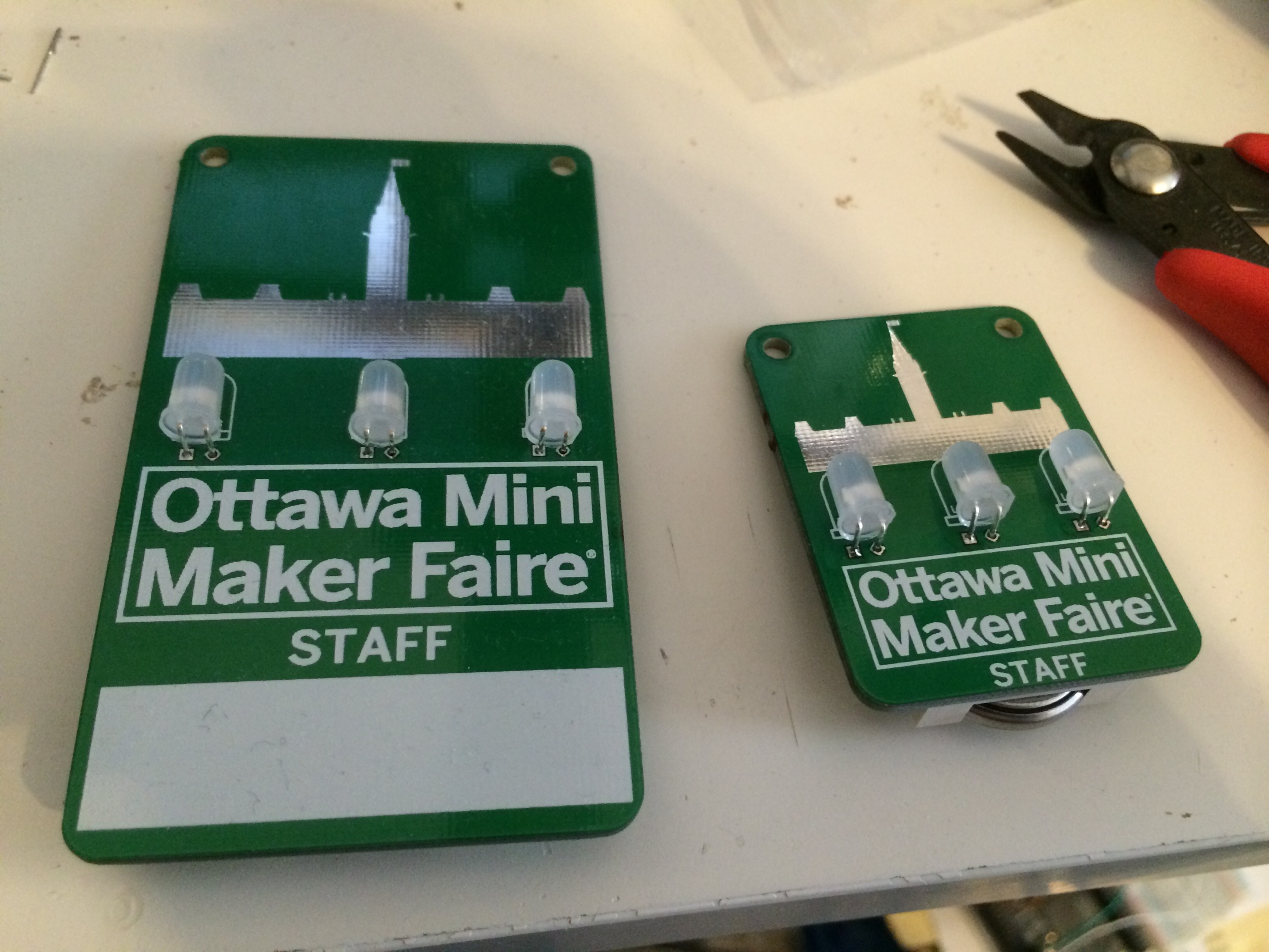
There were initially two designs: the small and the large. The small one was meant to be worn as a button, with a pin backing. It’s 1.95” by 1.45”, so it fits within Seeed Studios’s 5cm x 5cm maximum size. It doesn’t have a writing area on it, but does have two small (3.2mm) holes for a lanyard. The larger prototype was 3.4” by 1.95” and had a writing area, but was otherwise identical to the smaller one.
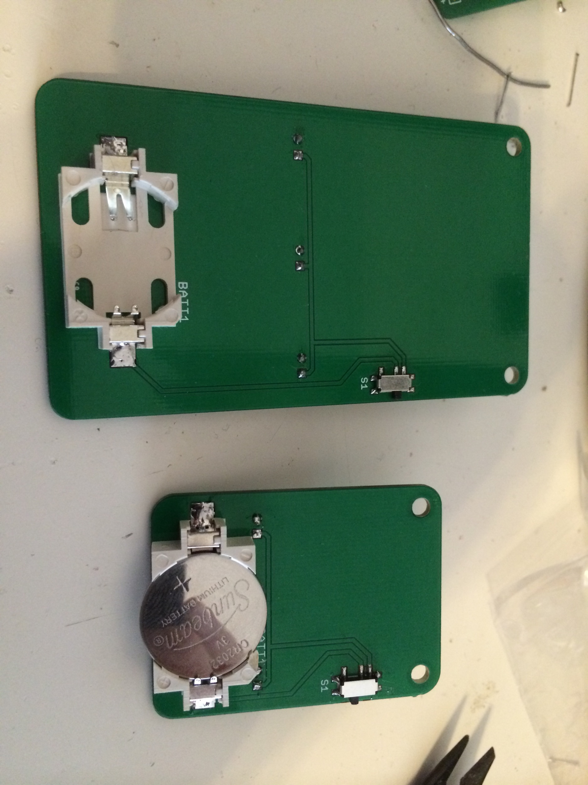
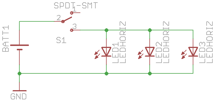
Electrically, the badge is incredibly simple - a 3V battery holder (CR2032), a switch, and 3 LEDs in parallel. This is actually much too simple, really - the LEDs should each have a current limiting resistor. This decreases the brightness slightly, but decreases the initial current draw dramatically, depending on the forward voltage of the LEDs in use. It also ensures that the LEDs are of comparable brightness - otherwise one or two will be substantially dimmer than the other(s), because the characteristics of different LEDs can differ wildly. I made the decision, however, to omit these, for two reasons:
- I was planning on using LEDs with a forward voltage around 3V so the effects should be diminished, and
- It would save a TON of time if I didn’t have to solder in 600 resistors as well.
Construction
The badges were build first by soldering the battery holder to the back. This has nice big tabs and pads on the board, so it was easy, but to ensure that the battery holder stayed in place both during assembly and afterwards, I used some scrapbooking glue dots on an applicator to affix them to the boards. The specific one I used was an Ad Tech Dot Glue Runner, which is purple.

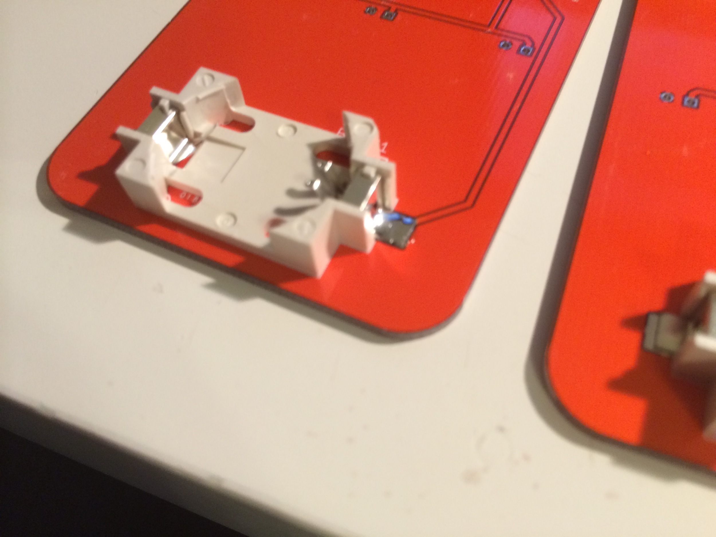
Next, the tiny SMD switches get soldered on. You get good at these quickly when you do a couple hundred of them.
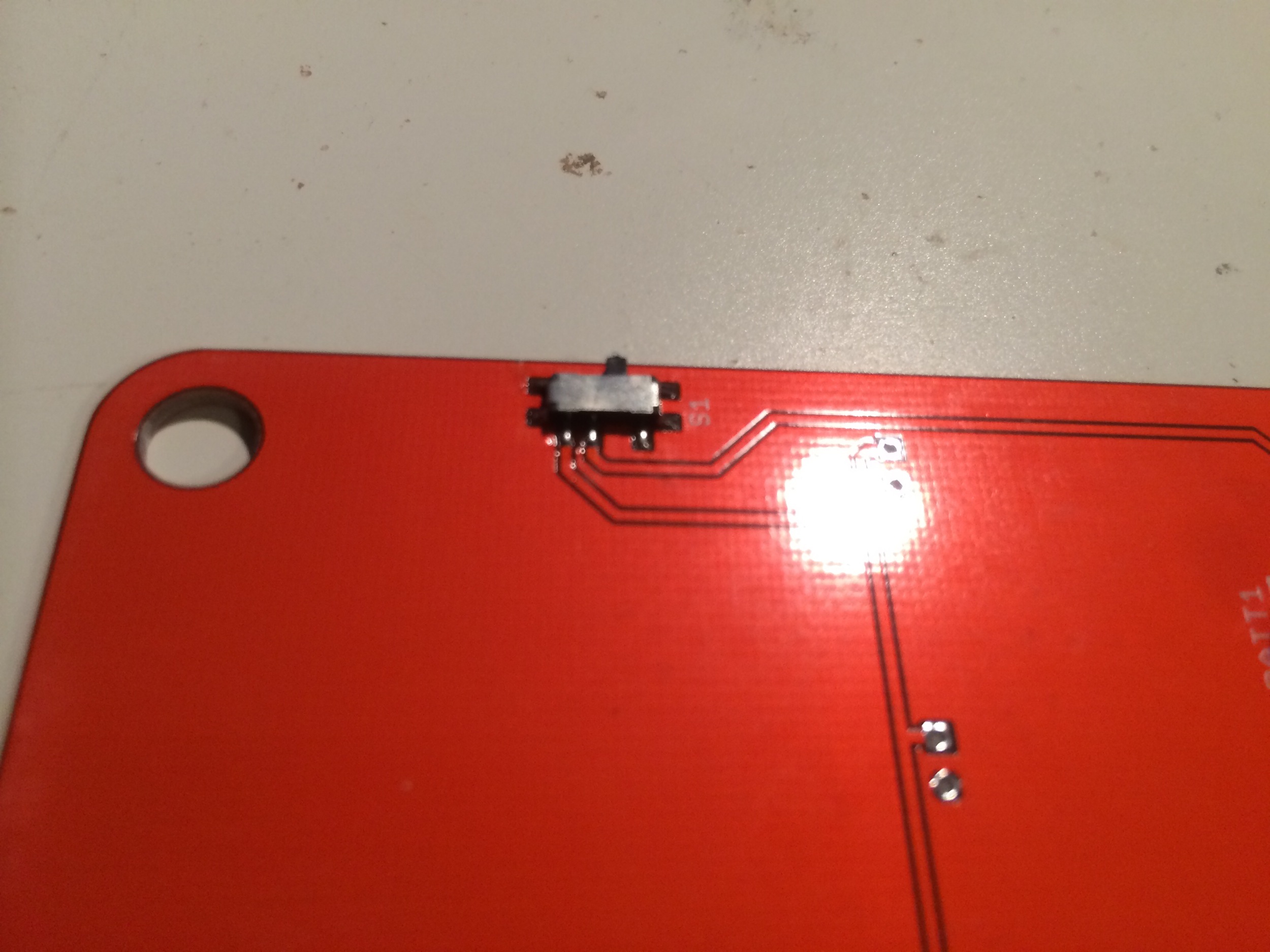
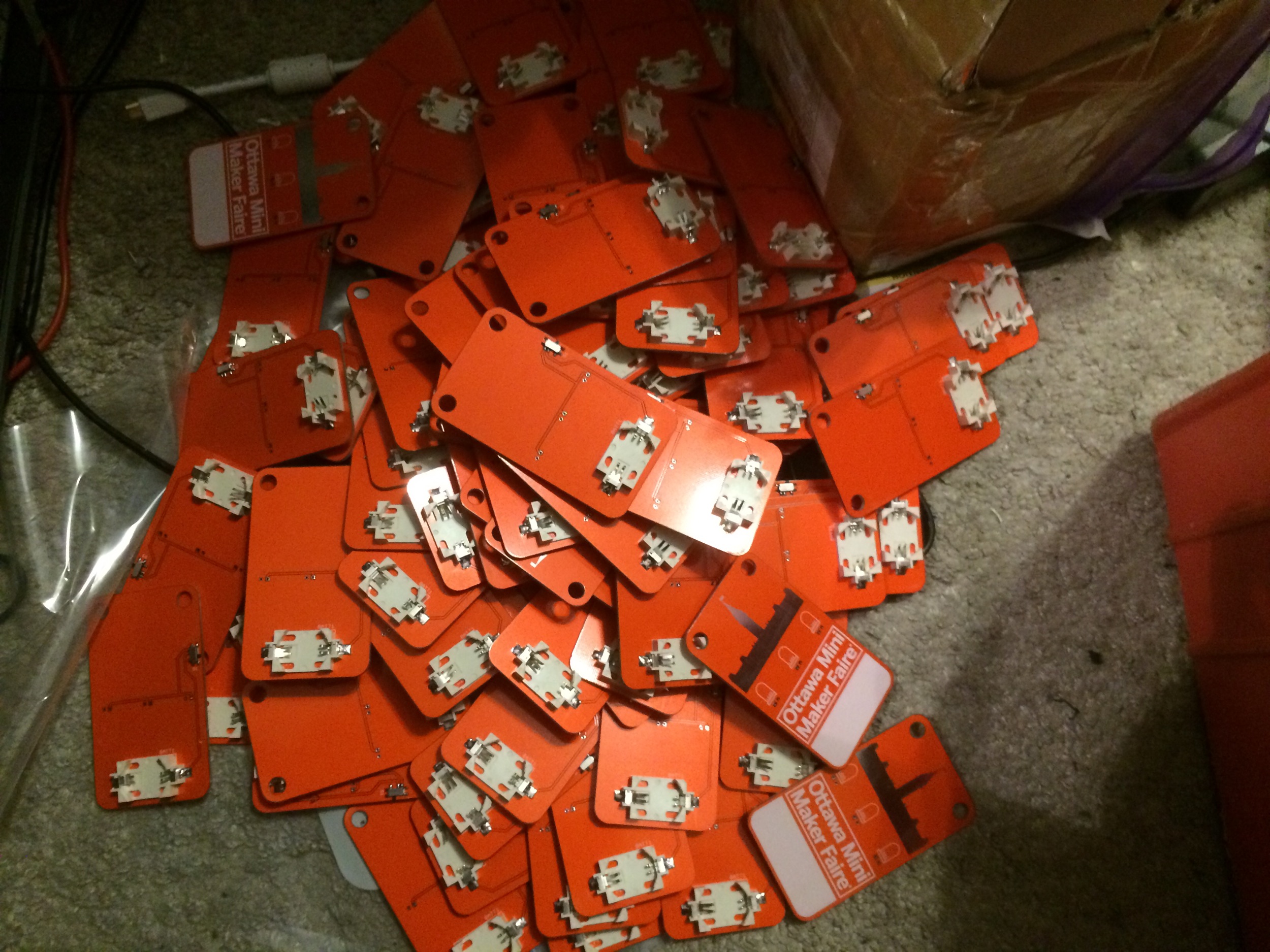
Once you’re done mounting those, the board joins the others in the pile on the floor.
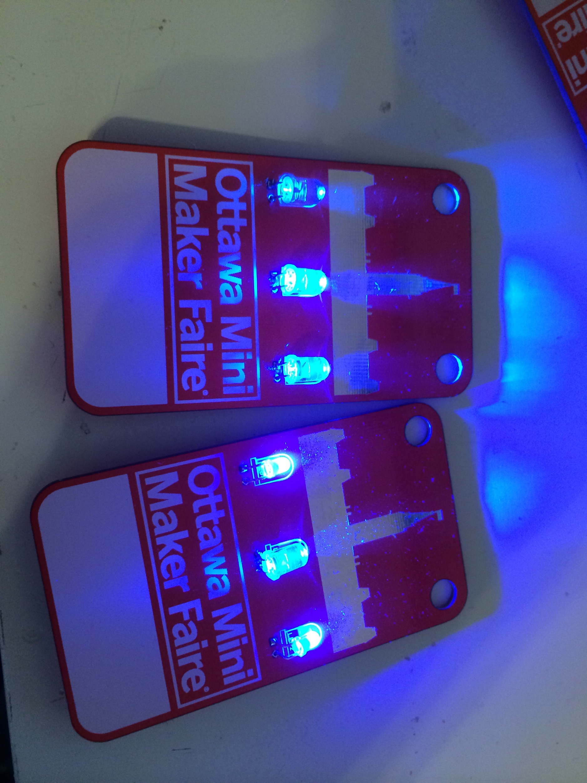
Once the numbers for how many of which colour started coming in, the LEDs went on. For the Maker ones, we went with a 5mm Blue LED in the middle, angled down to have a spotlight effect on the Peace Tower, and also to avoid blinding the wearer as much as possible. The two side ones were lovely diffused 3mm Blue LEDs that I previously used on my Christmas ornaments. All of these LEDs came from my personal stores / junk bin.
Partner badges got diffused colour-fading LEDs that I had for another project, and Staff badges got white LEDs that I never actually tested, but we only needed 2 of these badges. All told, it took a couple of evenings to do the battery holders and switches, and then 3 more to do all the LEDs.
Artwork
Handling the artwork on the board is a bit tricky. I have a technique, though:
- Prepare the art you need in your favourite drawing program (or whatever’s available). I used Paint.NET in this case. I usually try and set the dimensions of the artwork based on rendering it to the PCB at 300 DPI - so if I want the final product to be 2 inches wide, I make it 600 pixels wide. Make sure the artwork is black and white.
- Save it as a BMP file. Odds are you won’t be able to save it as a monochrome BMP - that’s fine.
- Open the BMP file in Microsoft Paint, and save it as a Monochrome BMP file.
- Launch EAGLE, and create a library for your artwork.
- Create a new package for the artwork.
- Type “run import-bmp.ulp” in the command line in EAGLE and hit enter.
- Open your BMP file, and select Black as the colour you want to import.
- Set the scaling mode to DPI, and use whatever DPI value you used in step 1.
- Set the starting layer to 25 (top silkscreen) to put the artwork on the top silkscreen, or 29 (tStop) to put it on the solder mask.
- Hit Run.
- Zoom in and delete the filename text in the lower left hand corner.
- Save the library and add the package for the artwork to the board layout.
Note that this is mostly from memory - I reserve the right to come back and revise this to be accurate.
Design files
The design files - done in EAGLE CAD 5.12.0 - have been released on Github. Use them in good health.
https://github.com/SurrealityLabs/mmfobadges2014
Results
The badges went over really well, and it was incredible seeing so many people using something I’d made in one place. If you look at different photos of the Faire and see a blue glow on someone’s face, odds are they were a Maker :)

- Nuit Blanche’s photos - lots of blue glow there
- Maker Faire Ottawa’s Twitter stream - even more blue faces
- CTV Ottawa’s coverage - blue badges in motion! Also, the Pinball machine is there for like ten frames.
I got a lot of compliments about the badges, and some ideas from people for next year. I’d like to do something a bit more hackable - ideally something with a microcontroller - but I need to figure out what we can actually make it do, and still stay within a budget, both in terms of power and price. Having 200 people with a pair of AAAs hanging from their necks all day might not be so welcome, so staying with a CR2032 is ideal. Next time we’re also definitely using pre-made lanyards - they’re cheaper and less injury-prone for me.
In terms of changes, I would have liked to order things earlier so that we could have avoided paying for fast shipping (and then paying the shipping charge again in the form of HST and fees for charging HST). Also, I would have definitely added current-limiting resistors - towards the end of the first day I was seeing LED brightness differences which they would have prevented.