Passcode Lock: Open Hardware Advent Calendar Day 1
Our first project in the Open Hardware Advent Calendar is the Passcode Lock. This is a project I recently completed for the Next Super Geek Challenge at Maker Faire Toronto 2014.
Overview
As part of the challenge, the participants had to find a code, and make sure they had the correct one at the challenge’s booth. The system that the organizers had wasn’t quite finished, so I offered to try and put something together with parts I had at home.
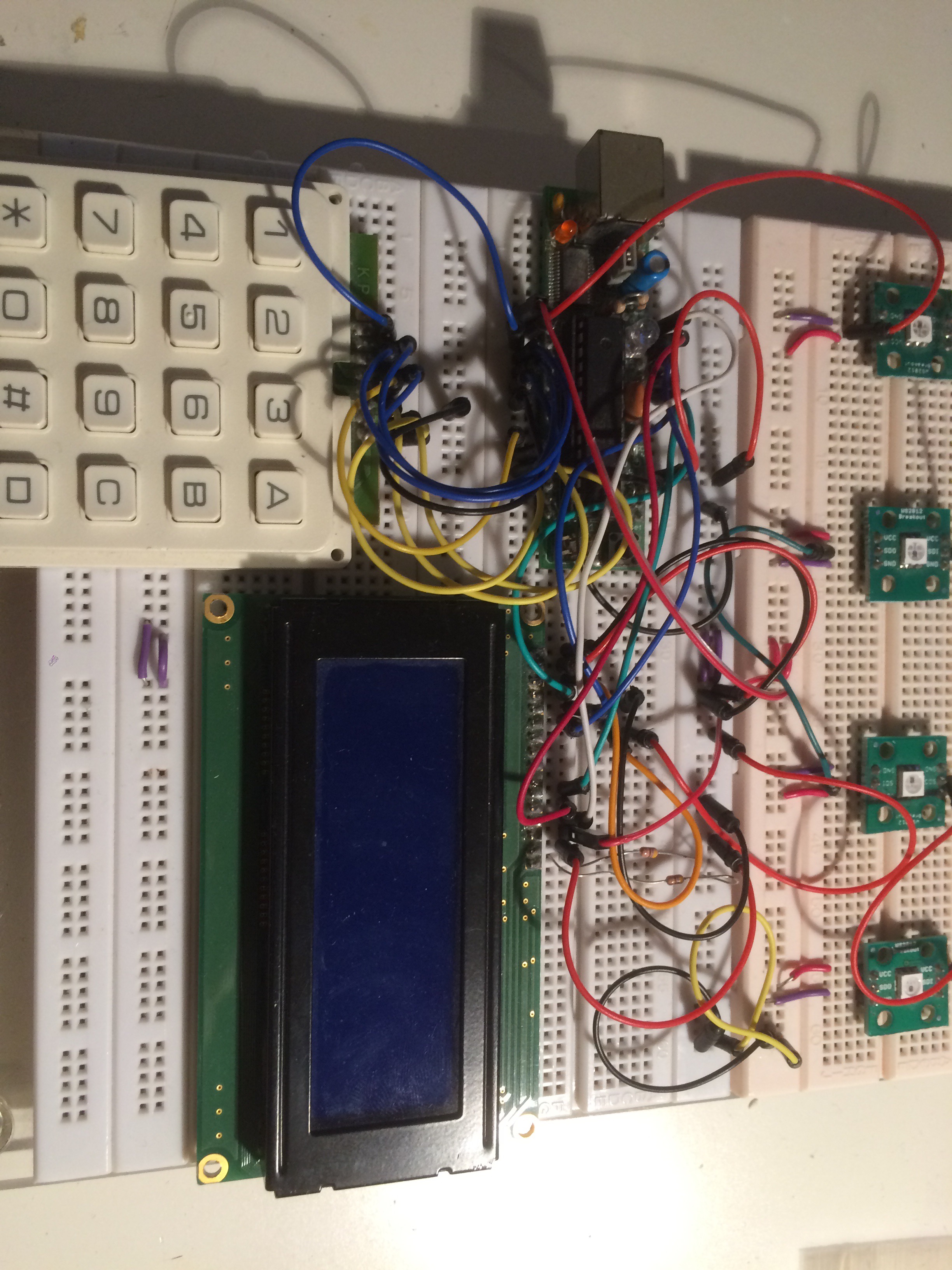
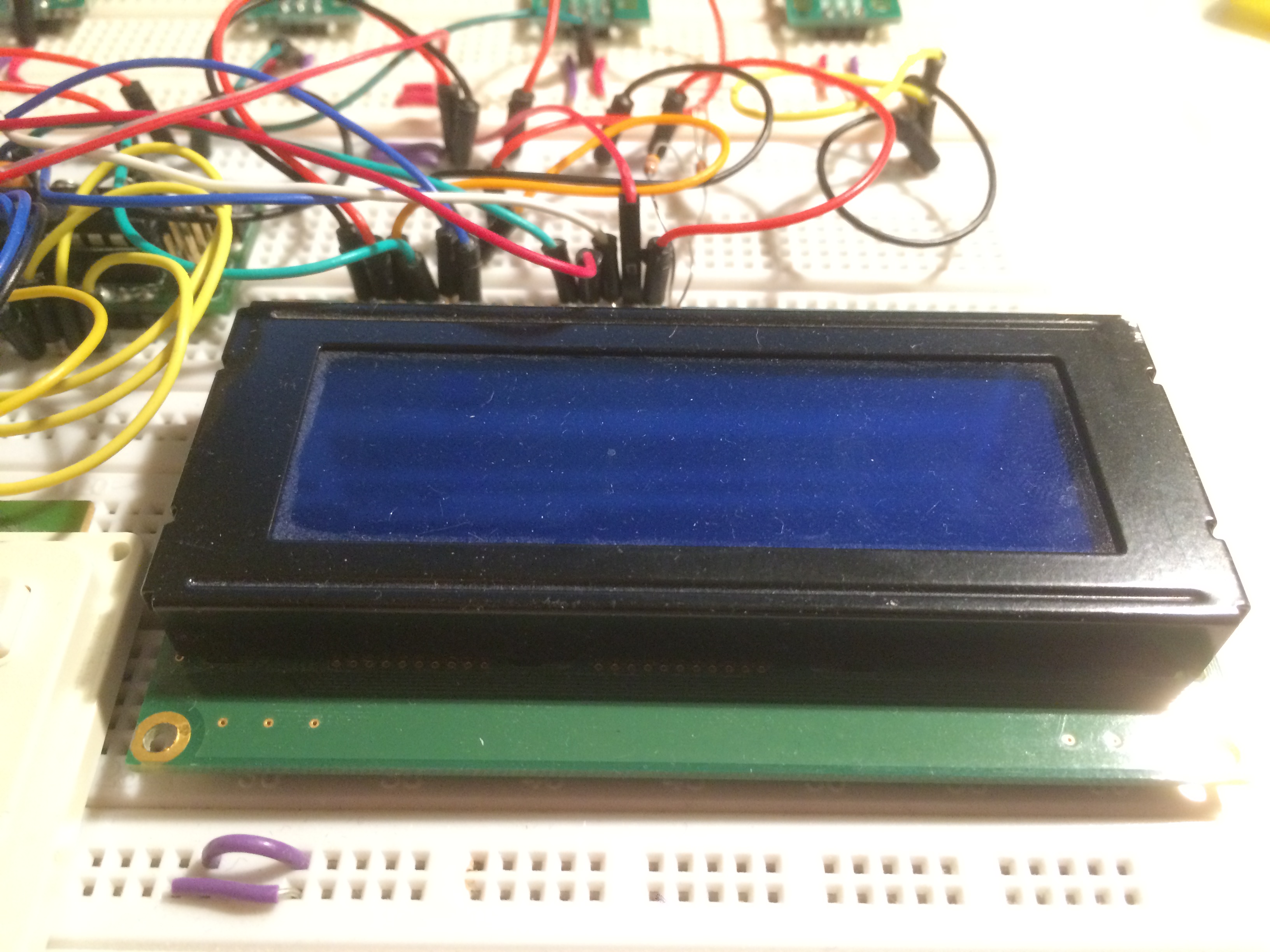
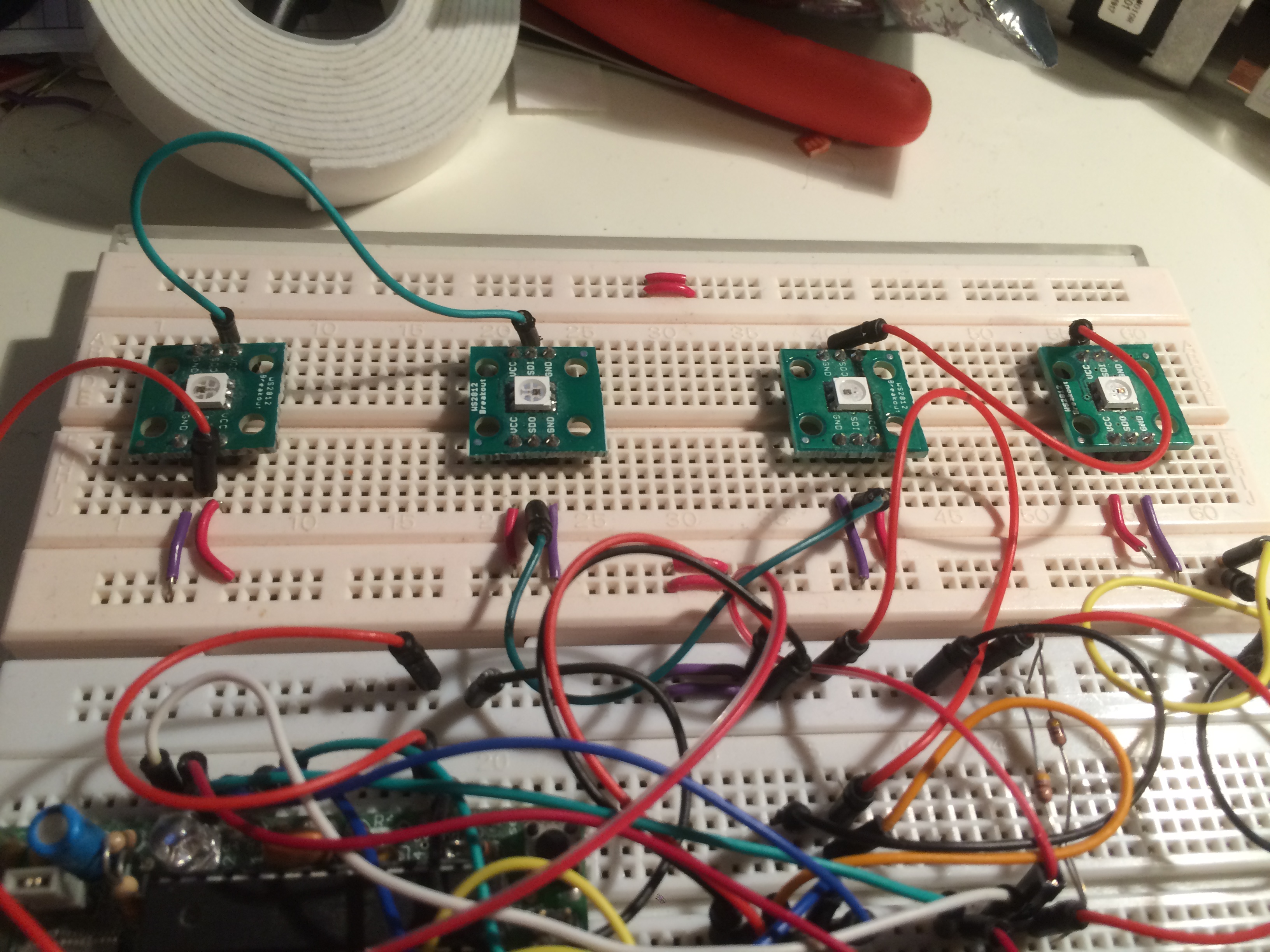
The project has a keypad, an LCD screen, an Arduino, and some RGB LEDs (WS2812s / NeoPixels, to be more precise). The LCD shows a message asking the kids to enter their code with the keypad. When they’re finished entering the code, if they’re right, they see a message and some blue lights. If they’re wrong, they see a different message, and some red lights.
Parts list
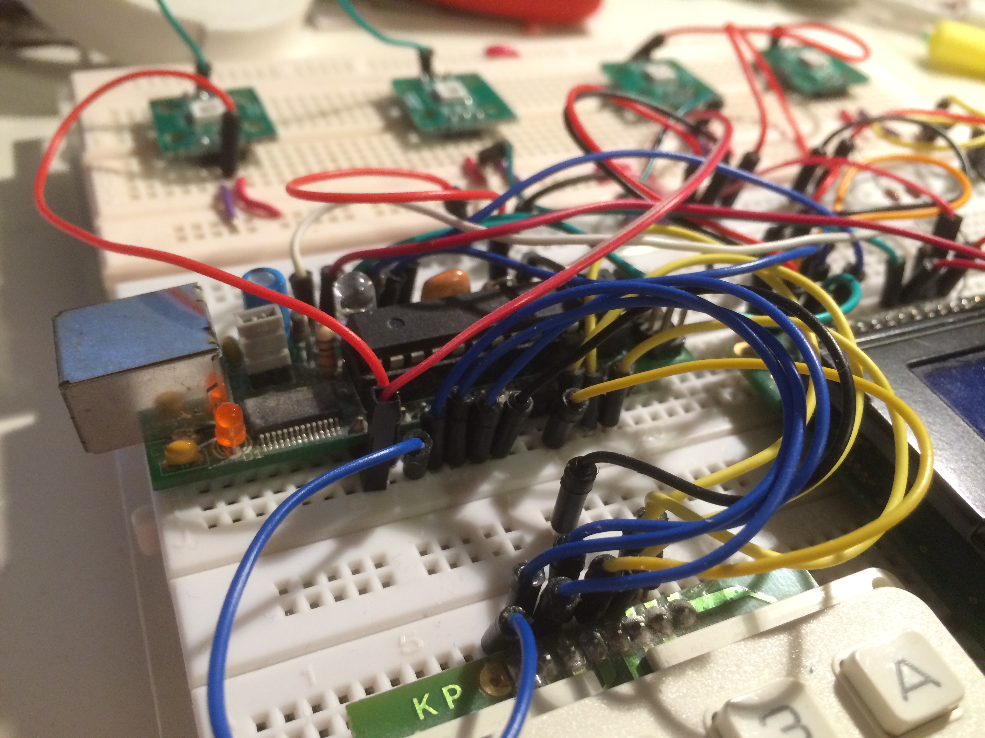
- 1 Arduino (I used a USB Boarduino, but just about any Arduino should work)
- 1 20x4 Character LCD with parallel interface (using the HD44780 or compatible controller - if it has 14 or 16 pins, it’ll probably work)
- 1 100 ohm resistor
- 1 10K ohm potentiometer (this comes with the Adafruit LCD)
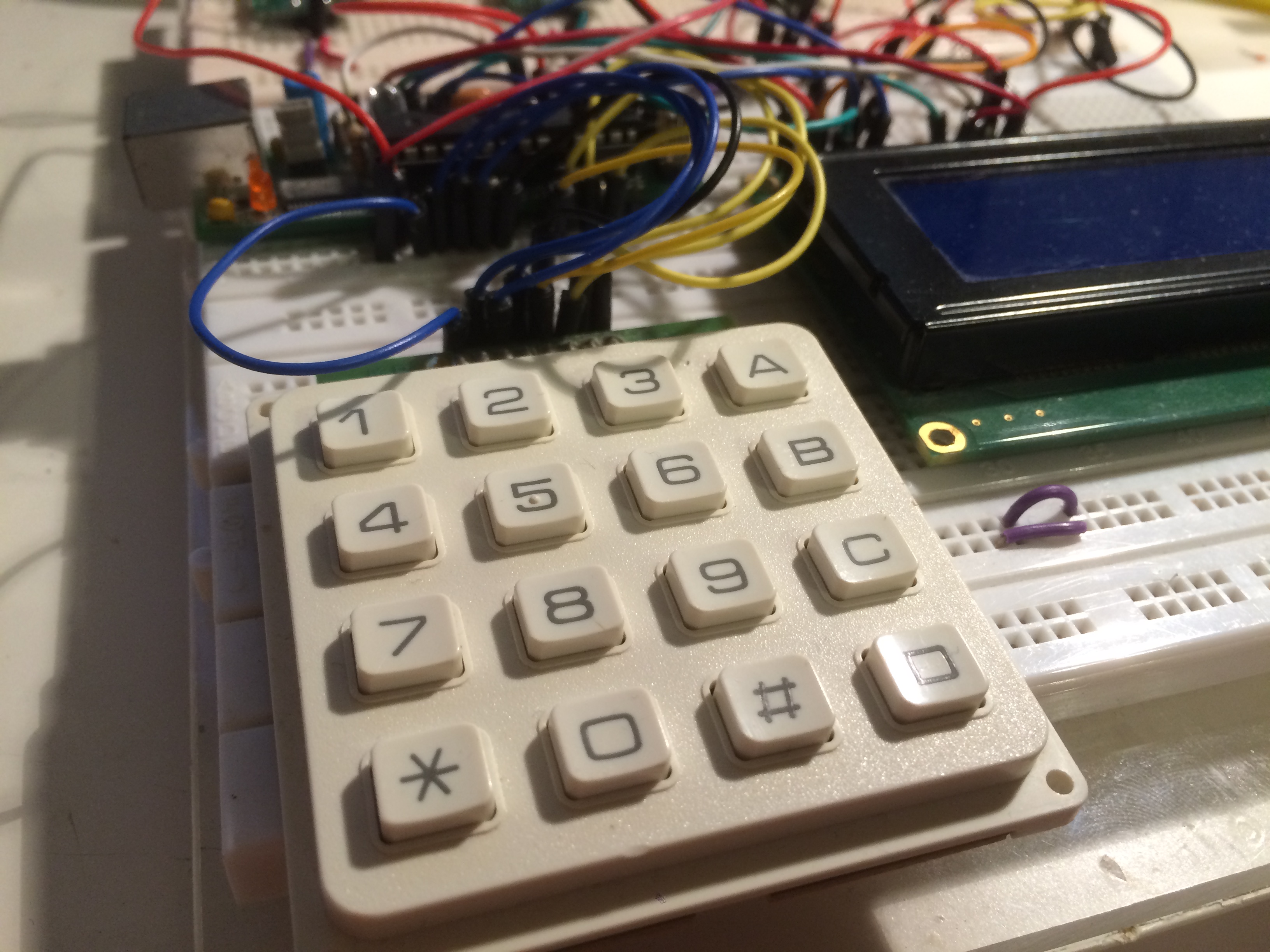
- 1 4x3 or 4x4 keypad
- 1 Breadboard
- A bunch of hookup wires
- 4 NeoPixels (I used my own design, but the Adafruit ones will work just as well)
Building the hardware
This is a fairly simple project, so I’m just going to present a Fritzing project showing the breadboard setup. I’ve used a 16x2 LCD in the Frizting project, because that’s all I found in the parts included. You should use a 20x4 LCD.
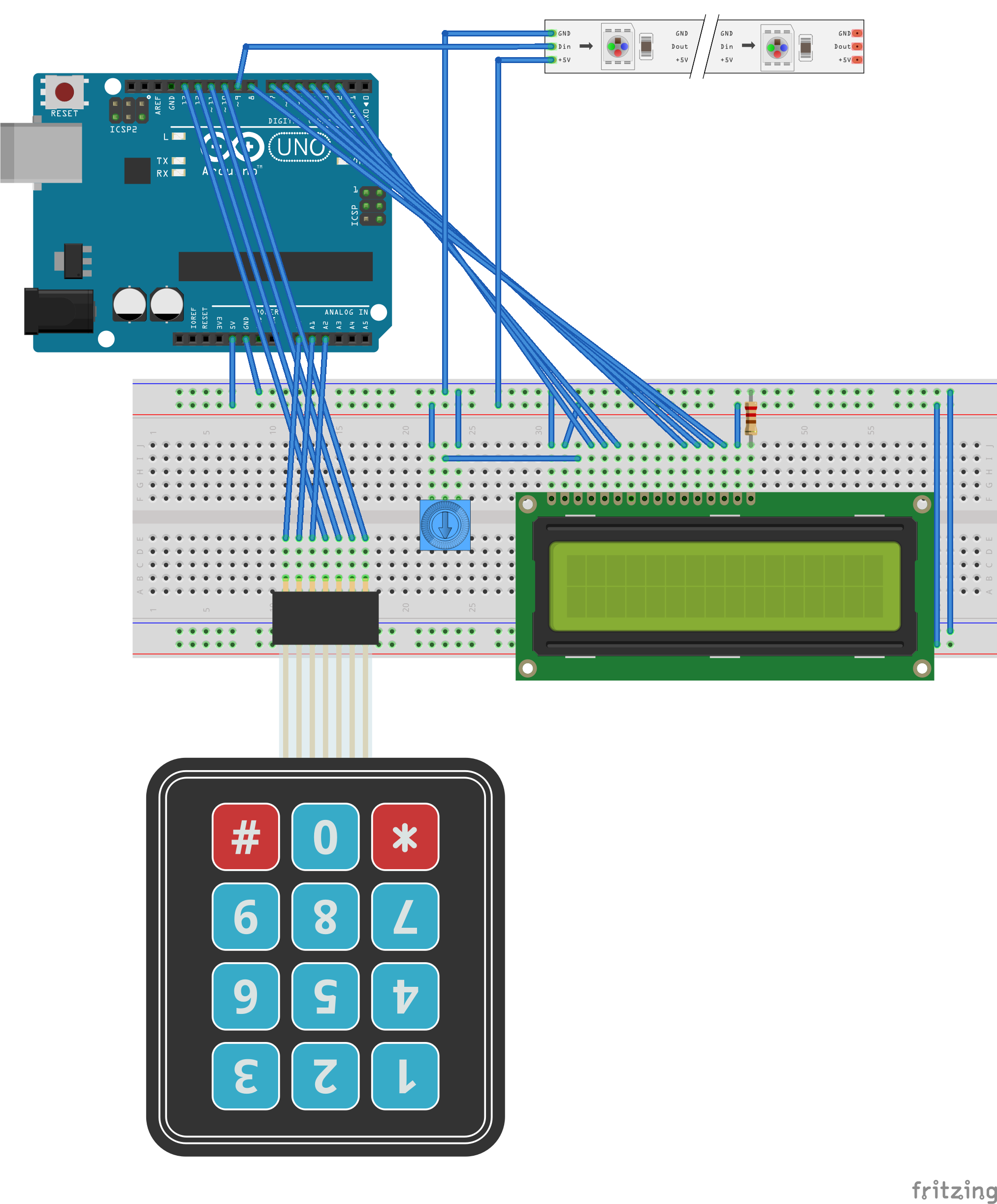
You can download the Fritzing project and Arduino code here, or check it out on GitHub.
The basic setup is this:
- LCD pin 1 to ground
- LCD pin 2 to +5V
- LCD pin 3 to the middle pin on the potentiometer
- LCD pin 4 (RS) to Arduino Digital Pin 2
- LCD pin 5 (R/W) to Arduino Digital Pin 3
- LCD pin 6 (E) to Arduino Digital Pin 4
- LCD pin 7-10 not connected
- LCD pin 11 (DB4) to Arduino Digital Pin 5
- LCD pin 12 (DB5) to Arduino Digital Pin 6
- LCD pin 13 (DB6) to Arduino Digital Pin 7
- LCD pin 14 (DB7) to Arduino Digital Pin 8
- LCD pin 15 to +5V
- LCD pin 16 to the 100 ohm resistor
- Other pin of 100 ohm resistor to ground
- NeoPixel +5V to +5V (for all of them)
- NeoPixel ground to ground (for all of them)
- NeoPixel #1 DIN to Arduino Digital Pin 9
- NeoPixel #2 DIN to NeoPixel #1 DOUT
- NeoPixel #3 DIN to NeoPixel #2 DOUT
- NeoPixel #4 DIN to NeoPixel #3 DOUT
- Keypad Row 1 to Arduino Digital Pin 10
- Keypad Row 2 to Arduino Digital Pin 11
- Keypad Row 3 to Arduino Digital Pin 12
- Keypad Row 4 to Arduino Digital Pin 13
- Keypad Column 1 to Arduino Analog Pin 0
- Keypad Column 2 to Arduino Analog Pin 1
- Keypad Column 3 to Arduino Analog Pin 2
- Keypad Column 4 (if you have it) to Arduino Analog Pin 4
Software Setup
The software makes use of the Keypad library, Password library, and Adafruit NeoPixel library. You’ll need to install them in your Arduino software - some instructions are available here. It also uses the LiquidCrystal library, which is included with the Arduino software. You should use a relatively recent version of the Arduino software - I was using 1.0.5r2.
The software is based on some other examples I found online - specifically http://www.instructables.com/id/Password-Lock-with-Arduino/ and http://www.tech-zen.tv/episodes/shows/make-it-work/episodes/keypad-input-to-an-arduino-episode-11. I made some modifications to clean up the menus a bit, to use the keypad for the “enter code” button, and to add the NeoPixels.
One interesting thing about this project is that it uses the Arduino’s Analog lines as Digital lines. Not many people know this, but they can be used for Digital I/O, so if you need more than 13 Digital I/O lines, just remember that Analog 0 is also Digital 14, Analog 1 is Digital 15, etc.
You can download the code from here along with the Fritzing project. You can check out the GitHub project here. After installing the libraries above, open the sketch in the Arduino software, customize the code, and download to your Arduino. You can change the code in the following line:
Password password = Password( “2008” );
Change the 2008 to whatever number you want - I’m not sure how long it can be, but 10 digits should be no problem.
Future improvements
I don’t have any future improvements planned on this project at the moment, but there are definitely some places it could be taken. Most improvements would probably require freeing up some I/O lines, as we’re kind of using all of them. Using an I2C LCD backpack like this Adafruit one would do the trick - note that Analog 4 and Analog 5, which are also the I2C port on the Arduino, have been left free for this reason.
Once some I/O lines are freed up, it would be pretty easy to add more lighting, some sound effects, and maybe even a servo to control a locking mechanism. More NeoPixels can easily be added just by chaining them onto the ones already there - some software changes are all that’s needed for those.
Conclusion
This is a pretty simple project - I put it together in a little over an hour by pulling together some spare parts and some pieces of other peoples’ code. The parts that it’s made of aren’t too intricate, so it’s fairly easy to assemble, but still a lot of fun.