DigitNet 2: Open Hardware Advent Calendar Day 10
Today’s project is another one that’s been waiting to be released for quite some time: a networkable 7 segment display that I call DigitNet 2.
Overview
Way back in 2007, as a final year “prank”, my graduating class made a clock to count down to the Iron Ring ceremony at McMaster University every year. We went with a bunch of discrete LED-based digit boards, each with a microcontroller, and networked together over RS485 with a control board. The final result worked, but I felt the design could be improved. Calling that one DigitNet 1, this project - DigitNet 2 - is an attempt to improve on that design.


There are a bunch of changes, but the major ones are moving to a proper LED driver chip (the STP08DP05 in this case), using 12V rather than 5V to drive the display, better wiring, and adding a configurable address to each board.
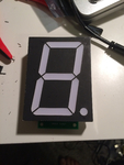
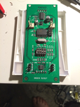
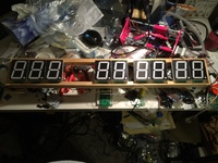
The end result of these improvements is a board that has a 4” 7-segment display unit (sourced from eBay), a proper constant-current LED driver chip, an ATTiny2313 microcontroller, a surface mount DIP switch to set the address for each board, some debug LEDs, and in and out connectors to wire the boards together easily. Having multiple boards makes it easy to do a big countdown clock (as you can see above, pictured on the incredibly messy desk / workbench)
Hardware
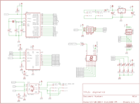
The hardware is fairly basic: an ATTiny2313 is connected to an SN75176 RS485 transceiver. Its address is configured by a surface-mount DIP switch. There’s a basic power supply to give 5V for the digital parts, and 12V powers the LED display. This display has multiple diodes in series in each segment, so a larger voltage than normal is required to drive it.

The board is designed to use as many surface mount parts as practical, and to mount to the back of the 4 inch 7 segment display module. It was also designed to fit in a 5cm x 10cm Seeedstudio prototype board order, and provide mounting holes to secure the module to whatever frame it needs to attach to.
To wire together a bunch of boards, the power and network connections are daisy-chained between boards, with a controller of some sort at one end.
Schematic, PCB and Gerber files can be downloaded from our GitHub.
Software
The software was written in C for the AVR using the standard AVR-GCC toolchain. An ISP connector is provided on the board to load the firmware onto the chip. The software basically sits waiting to hear one of three commands, and then listens for an address (for some commands) and then a byte of data. That data is either the segments to turn on (7 segments plus one decimal point = 8 bits), or the brightness. Brightness is controlled using the PWM output of the microcontroller.
Software can be downloaded from our GitHub.
Protocol
There are three commands:
- 0x99 is Global Brightness Change. Every node on the network acts on this message regardless of address, and sets the PWM duty cycle to the next byte received.
- 0xAA is a Data command. The next byte specifies which board the message is meant for. The protocol supports up to 256 units, but only 4 bits are implemented in this version - the DIP switch drives the lower 4 bits, and the upper 4 are set to 0. The last byte specifies which segments to turn on. I don’t have which bits map to which segments available at this time.
- 0xBB is a Brightness command. The next byte specifies which board the message is meant for. The last byte specifies the brightness for that digit.
Data is transmitted over RS485 at 9600bps, 8 data bits, 1 stop bit, no parity.
Future enhancements
These work fairly well for making a big-digit display - I easily made a countdown clock with them - but the protocol could do with a checksum of some sort for integrity. I also need to document said countdown clock.
Conclusion
This was a successful project, as far as making an enhanced version of the original at McMaster - it was far easier to configure, assemble and maintain than the original.
