Project Vending Machine 1.0
Introduction
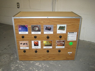
The Project Vending Machine is a vending machine for digital goods - files, specifically. Vending Machine is a bit of a misnomer, actually - no money changes hands in this implementation, but vending machine is about the closest analog that we could come up with.
It’s pretty simple to operate - you plug a USB thumb drive into the USB port in the front, pull the knobs to select the projects you want - kind of like an old cigarette vending machine - and hit a button to copy them. A light for each project tells you if it’s selected, if it can be copied, if it’s copying, if it’s done or if there was an error.
How it came about, I’m not entirely sure. At some point, we determined that it would be useful to be able to distribute digital files from a vending machine. I can’t say for sure what sparked it, but it may have been restrictive download caps. At any rate, we didn’t find anything like this that existed, and figured it could be useful for giving out project details at Maker Faire.
So we decided to make one for Maker Faire Detroit 2011.
Architecture
We investigated a few microcontroller-based methods of building it, but actually building that would be complicated and likely have compatibility issues. I wound up buying an Insignia Infocast 3.5 - a Chumby relative - at a good price at Best Buy. It runs Linux, has various ways of attaching buttons, and has USB support, so it would suit the system nicely.
We determined that the system would need:
- 1 selector per project
- 1 RGB status LED per project
- 1 overall "Copy" button
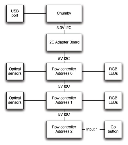
We decided that 8 projects would be an appropriate number, arranged in 2 rows of 4. We went with a row controller PCB for each row of 4. Given 3 outputs for each status LED and one for the input, this meant 16 lines total per board. This fit perfectly with the MCP23017 I/O expander from Microchip, which would allow us to chain mutiple devices from the Infocast’s I2C serial bus. Up to 8 MCP23017s can be added, which would mean up to 32 projects per vending machine. The start button was to be hooked up to one of the Infocast’s built-in GPIO pins.
The overall architecture was meant to look like this:
This approach had a few big advantages:
- Linux-based, so a lot of it could be prototyped easily on a desktop machine before adding the hardware-specific stuff later
- Infocasts were somewhat available at that time, so we could each have one to work on
- Having Linux as a base meant a wide variety of programming languages available to us. We wound up going with a combination of C and BASH.
- Having Linux as a base also meant that the file handling stuff was already, well, handled.
- Using off-the-shelf I/O expanders meant that no firmware had to be written - only host software. Not having to write and debug firmware nor develop an over-the-wire protocol to communicate with that firmware saved a *ton* of time.
Hardware
The hardware consists of four major parts:
- The Infocast, with its I2C and I/Os broken out via a ribbon cable.
- The interface board, which the Infocast connects to, and has an I2C level shifter (the Infocast uses 3.3V, and the other boards were run on 5V)
- The row controllers, which have the I/O expanders and the LEDs
- The optical sensors for the knobs
I’ll describe each individually.
Infocast
We did two main things with the Infocast: Replace the SD card with a larger one (described later), and soldering in a ribbon cable to bring out the I2C, a GPIO pin and the UART (for debugging). I don’t have a ton of details on how we did the cabling, but I do have the following photos:
Interface board
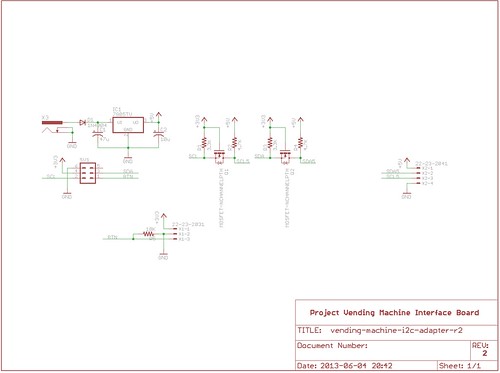
This connects to the ribbon cable, and level shifts the I2C. It then connects to the row controllers. The level shifter is a standard N-MOSFET based I2C level shifter, using 2N7000 transistors. The schematic is more or less like this:
Row controller
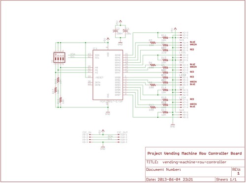
The row controller has the I/O expanders, some jumpers for the address of the board, connectors and current limiting resistors for the LEDs, and connectors and pullup resistors for the optical sensors. The schematic is as follows:
These were built on protoboards, but we do have PCB layouts that we never built. They’re included in the source code further down.
Optical sensors
To make the system robust and inexpensive, the knobs use a standard break-beam optical sensor with a dowel that slides between the light source and sensor. This way the user isn’t directly interacting with the sensor - making it a bit more robust - and is still fairly cheap. The setup looks like this:
We used a Sparkfun breakout with some holes drilled to mount it to the frame.
Software
The software consists of three key parts:
- Linux on the Chumby. This handles a lot of things - I2C driver, file handling, and even automatically mounting USB drives. About the only thing we changed here was upgrading the SD card in the Infocast / Chumby, which we followed instructions
here for.</li> - Programs to interact with hardware. These were written in C, based on samples posted to the Chumby forums. The source code for these is included in the download below.
- The overall control script, written in BASH. This was basically a state machine to run the overall process - it would turn on or turn off LEDs for each selected project. They'd be yellow if no USB drive was available, or green if one was. If the drive was available, the Start button would also be checked. Once it was pushed, the script would start copying files, turning the light purple while it was copying, blue if it was done, or red if it failed. It would do this for each selected project, then wait until the storage device was removed before resetting.
</ol> The source code is available for download here. To set it up, you'll need a Chumby or Infocast with developer tools installed - once you SSH into it, just try running gcc, and it should tell you how to get that going. Then, use the Makefile to compile the C programs. After that, edit the shell script to specify the project files. When you've got the unit hooked up to the hardware, run the script to operate the machine. It will output somewhat useful debug data as it runs to help determine what it thinks is going on.Construction
I don't have final plans for the overall machine. It was basically made of a few horizontal "slices" made from Select Pine 1x2s. Top and Bottom were basic rectangular frames, while the two middle ones - for the rows with knobs - had horizontal cross-members, and holes for both LEDs and the selector knobs / dowels. The cross-members were used to make sure that the knobs slid smoothly and straight. Sensors were put on the back edge of each slice, and the LEDs were attached behind the appropriate holes on the front. After these slices were assembled, they were combined with vertical 1x2s to form the overall box, which then had woodgrain-printed masonize attached to the sides, and MDF panels on the top and bottom. Aluminum trim was added for the 70s Cigarette Machine look. Holes were drilled for the LEDs knobs in the fron panel, and then everything was wired up. This was a pretty tricky construction technique that didn't result in anything even close to square or true, so I don't recommend it in future. That said, here are some photos of the process and the final product:


Lessions Learned and Conclusion
We learned a bunch doing this project. Using Linux as the basis made some of the tricky stuff really easy, but also made diagnosing I2C errors a bit harder. Having I2C over long distances with poor wiring was a BAD idea - lots of noise would lock up the bus, which made it stop responding and kept the Chumby from reading its configuration EEPROMs on start, making a reboot to clear everything and get it all working again somewhat invovled. So I2C with lots of wire should be avoided in future. We didn't get the GPIO-based start button to work, so we wound up using an extra row controller with a single button to do that. This required minimal modification to our scripts and worked pretty well. The frame was way too big and way too heavy for what it had, and was a pain to move in and out of the Faire. More than a few people remarked on how much it looked like a cigarette vending machine. The knobs with the optical sensors worked incredibly well, and were a great demo to show kids who were coming by. The Chumby proved to be a bad choice, once they stopped being available for sale not long after we showed off the project. It worked, but now the ability to duplicate it is severely restricted. The biggest surprise, though, was that next to nobody had a thumb drive to copy stuff to. Overall, though, it was a great project that was a lot of fun (though a bit stressful at the end) and was VERY well received. We liked it enough to do a bigger and better version in 2012.


